Your cart
Choose your Location
-
Bintel Glebe
Usually ready for pickup in 24 hours
Bintel 84 Wentworth park road, Glebe, 2073, NSW
Phone:(02) 9518 7255
Hours:
Monday9:30 am–5:30 pm
Tuesday9:30 am–5:30 pm
Wednesday9:30 am–5:30 pm
Thursday9:30 am–5:30 pm
Friday9:30 am–5:30 pm
Saturday9:30 am–4 pm
SundayClosed
Products eligible for discount
1809 products
1809 products
Sort by:
- Featured
- Most relevant
- Best selling
- Alphabetically, A-Z
- Alphabetically, Z-A
- Price, low to high
- Price, high to low
- Date, old to new
- Date, new to old

$689.00
Antlia ALP-T Dual Band 5nm Highspeed Filters are optimized to work with high-speed imaging systems by shifting slightly the passband and center wavelength. Using these highspeed filters between optics f/2.2 and f/3.6 shows much stronger and more contrasted in nebulae imaging compared to the standard version, if you seek the best possible performance with any optics faster than f/2.2, the highspeed version is the best choice.
But keep in mind, the blue shift data by the computer simulation indicates narrowband filter shifts its bandwidth to shorter wavelengths with faster optics than f/2, transmission at the emission wavelength may decrease perhaps 15%-20%. Although the Antlia ALP-T highspeed filter has similar transmission rates reduction in the H-a and OIII when the filter is used on fast optics, based on current standard version users’ data, it is evident that the filter still has the high performance of increase in emission nebula contrast and minimized halo.
The highspeed version price is the same as the standard filters and double benefits for the high-speed optics users. Worth mentioning is that Antlia inspected and measured products piece by piece with one of Agilent Cary’s professional spectrophotometer, resolution/slit width is up to 0.2nm, which make us provide highly reliable and consistent products to you.
The Antlia ALP-T dual band 5nm series filter is a dual line-pass filter that was designed to be used primarily with one-shot color (OSC) cameras such as DSLR's and astronomical OSC cameras. It can also be used as a narrowband filter for monochrome cameras to save imaging time. The advanced multi-coatings on our ALP-T ultra dual band filter effectively isolate the red Ha and the blue-green OIII lines light from emission nebulae, with almost total suppression of optical density (OD)4.5 on unwanted wavelengths from light pollution, moonlight, and airglow. The result is that our ALP-T dual band 5nm filter creates a superior signal-to-noise ratio and better contrast in your images.
The filter enables the capture of the two main emission nebulae bands at the same time, whilst suppressing unwanted light pollution. It enables you to capture cleaner data and reduces the post-processing efforts to isolate faint details from the background light pollution.
Application and Performance:
Designed especially for fast astronomy optics, in particular f-ratios f/2.2 to f/3.6
Engineered specifically for use with DSLR, CMOS, and CCD color cameras
Suppression of optical density (OD)4.5 on unwanted wavelengths adds signal-to-noise
Extremely steep bandpass edges minimize internal reflections
Ideal flat-top and moderate bandpass reducing spectrum down shifts
Ion Gun Assisted Deposition coating technology on the double-sided polished substrate making it the most consistent and accurate light pollution suppression filter
Designed to suppress artificial lighting from Bortle scale 1 to Bortle scale 8
Near IR (NIR) is blocked up to 1050nm
Technical Specifications:
| Hydrogen-alpha | Oxygen III | |
| FWHM | 5nm | 5nm |
| CWL (Central Wavelength) | 657.8nm | 502.2nm |
| Peak Transmission | 88% | 82% |
| Blocking | ≥OD4.5 @ 300-1050nm | |
| Filter Thickness | 2mm+/-0.05mm | |
Filter Ring:
2'' (M48*0.75)
Ultra-thin filter cell to minimize vignetting by maximize possible clear aperture
Black Anodized Finish
Laser Engraving No Fading
Spectrum Curve:
Not Recommended:
Solar imaging
Night visual observation
Not Permitted:
DO NOT LOOK AT THE SUN WITH THIS FILTER
Serious eye damage will result if you fail to observe the warning

QHY5III678 is a new planetary and guiding camera of the 2nd generation of QHY5III series, the upgraded version of QHY5III178M/C, with excellent near-infrared high sensitivity.
In this latest generation of sensors, the photodiode portion of the pixel well is physically deeper than in previous sensors, allowing photons of longer wavelengths to penetrate deeper into the substrate. This dramatically increases the sensor’s sensitivity to red and near-infrared (NIR) light. The sensor displays almost equal peak sensitivity to NIR light as it does to light in the visible spectrum.
DDR3 512MB
The QHY5III678 series planetary and guiding cameras are all equipped with a 512MB DDR3 image buffer which can effectively reduce the pressure on computer transmission, a great help for planetary photography which often requires writing a large amount of data in a short period of time. Some deep-sky astrophotography cameras on the market today only have 256MB, for example.
In comparison, the 512MB DDR3 memory of the new 5III (Ver. 2) series cameras represents a significant upgrade.
USB-c connectivity
Tips: It is recommended to use the official standard Type-C data cable of QHYCCD. As the market is flooded with a large number of poor-quality Type-C cables, casual use may lead to the camera malfunctioning. If you use your own spare cable, please make sure it is a high-quality cable.
Universal Guiding Interface
The custom interfaces of the previous generation of planetary cameras and guiders has been replaced in the QHY5III (Ver.2) cameras with a more universal ST-4 compatible guiding interface. Now, even if the guiding cable is lost or damaged, you will be able to easily get a replacement on the market at a low cost.
Indicator LED
Specifications
| Model | QHY5III678 |
| CMOS Sensor | Sony IMX678 |
| Pixel Size | 2.0um*2.0um |
| Effective Pixel Area | 3856*2180 |
| Effective Pixels | 8.4 Mega Pixel |
| Fullwell | 9ke- |
| Readout Noise | 0.57-3.3e- |
| AD Sample Depth | 12-bit (output as 16-bit and 8-bit) |
| Built-in Image Buffer | 512MB DDR3 Memory |
| ROI Frame Rate | Full Resolution 43FPS @8BIT 22FPS @16BIT
1080Lines 85FPS @8BIT 43.5FPS @16BIT 640Lines 140FPS @8BIT 71FPS @16BIT |
| Exposure Time Range | 11us-900sec |
| Shutter Type | Electric Rolling Shutter |
| Computer Interface | USB3.2 Gen1 Type-C |
| Guide Port | st4 |
| Telescope Interface | 1.25-inch, compatible with CS-port and C-port lenses by replacing the front-end connector (An IR AR glass and an IR850nm filter are included in the standard version.) |
| Back Focal Length | 17mm(with adapter); 8±0.5mm(without adapter) |
| Weight | 90g |
Camera Curves

Multiple Readout Modes
Multiple Readout Modes are special for QHY 16-bit Cameras (QHY600/268/461/411). Different readout modes have different driver timing, etc., and result in different performance. See details at “Multiple Readout Modes and Curves” Part.
Random change thermal noise suppression function
You may find some types of thermal noise can change with time in some back-illuminated CMOS cameras. This thermal noises has the characteristic of the fixed position of typical thermal noise, but the value is not related to the exposure time. Instead, each frame appears to have its own characteristics. The QHY600/268/461/411 use an innovative suppression technology that can significantly reduce the apparent level of such noise.
UVLO Protection
UVLO(Under Voltage Locking) is to protect the electronic device from damage caused by abnormally low voltages.
Our daily life experience tells us that the actual operational voltage of an electrical device must not significantly exceed the rated voltage, otherwise it will be damaged. For such precision equipment as cameras, long-term work at too low input voltage can also be detrimental to the working life of the camera, and may even make some devices, such as power manager, burn up due to long-term overload. In the all-in-one driver and SDK after 2021.10.23 stable version, the camera will give a warning when the input voltage of the camera is below 11V.
Optimizing USB Traffic to Minimize Horizontal Banding
It is common behavior for a CMOS sensor to contain some horizontal banding. Normally, random horizontal banding can be removed with multiple frame stacking so it does not affect the final image. However, periodic horizontal banding is not removed with stacking so it may appear in the final image. By adjust the USB traffic in Single Frame mode or Live Frame mode, you can adjust the frequency of the CMOS sensor driver and it can optimize the horizontal banding appeared on the image. This optimized is very effective to remove the periodic banding in some conditions.
A typical Periodic Horizontal Noise under certain USB_TRAFFIC values.
After Adjusting the USB Traffic to avoid the periodic horizontal noise.
Reboot the camera by power off and on
The camera is designed to use the +12V to reboot the camera without disconnecting and reconnecting the USB interface. This means that you can reboot the camera simply by shutting down the +12V and then powering it back on. This feature is very handy for remote controlling the camera in an observatory. You can use a remotely controlled power supply to reboot the camera. There is no need to consider how to reconnect the USB in the case of remote control.
Specifications
| Model | QHY461PH |
| Image Sensor | SONY IMX461 BSI CMOS Sensor |
| Pixel Size | 3.76um x 3.76um |
| Color / Mono Version | Mono Only |
| Image Resolution | 11760 × 8896 |
| Effective Pixels | 102 Megapixels |
| Effective Image Area | 44mm x 33mm |
| Sensor Surface Glass | AR+AR Multi-Coating Clear Glass |
| Full Well Capacity (1×1, 2×2, 3×3) | 50ke- / 200ke- / 450ke- in Standard Mode 80ke- / 320ke- / 720ke- in Extend Full Well Mode |
| A/D | 16-bit (0-65535 greyscale) for 1X1Binning18bit in 2X2 19BIT in 3X3 20BIT in 4*4 software Binning |
| Sensor Size | TYPICAL 3.4inch |
| Read Noise | 1e to 3.7e (in HGC mode) |
| Dark Current | Approx 0.003e/pixel/sec @ -20C |
| Exposure Time Range | 50us – 3600sec |
| Frame Rate | 2.7FPS @ 8BIT 1.3FPS@16BIT on USB3.0 2.7FPS @ 16BIT 6FPS @ 14BIT on 10Gigabit Fiber |
| Shutter Type | Electric Rolling Shutter |
| Computer Interface | USB3.0 |
| Filter Wheel Interface | 4PIN QHYCCD CFW Port |
| Built-in Image Buffer | 1GByte DDR3 Buffer |
| Cooling System | Dual Stage TEC cooler(-35C below ambient with air cooling). |
| Anti-Dew Heater | Yes |
| Telescope Interface | – |
| Optic Window Type | AR+AR High Quality Multi-Layer Anti-Reflection Coating |
| Back Focal Length | 32.5mm |
Camera Curves

$6,610.00
With the advantage of low readout noise and high-speed readout, CMOS technology has revolutionized astronomical imaging. A monochrome, back-illuminated, high-sensitivity, astronomical imaging camera is the ideal choice for astro-imagers. The QHY600M-L uses the latest SONY back-illuminated sensor, the IMX455, a full frame (35mm format) sensor with 3.76um pixels and native 16-bit A/D. This sensor is available in both monochrome and color versions. The QHY600 ends the days of non-16bit CMOS cameras and it ends the days non-full frame (and larger) monochrome CMOS cameras.
The QHY600M-L has extremely low dark current (0.002e/p/s@-20C) using SONY’s Exmor BSI CMOS technology. QHY600M-L is also a zero amplifer glow camera. The QHY600M-L has only one electron of read noise at high gain and full resolution and 4FPS readout speed. One electron of read noise means the camera can achieve a SNR>3 at only 4 to 6 photons. This is perfect performance when conditions are photon limited, i.e., short exposures, narrow band imaging, etc., making this large area sensor ideal for sky surveys, time domain astronomy, fluorescence imaging, DNA sequencing and microscopy.
Models
QHY600 Series have mutiple models which covers both photographic and scientific using. Below list different types of QHY600 PH (photographic) series:
QHY600PH : Standard version for amateur astrographers;
2GB DDR3 image buffer
In order to provide smooth uninterrupted data transfer of the entire 60MP sensor at high speed, the QHY600 has 2GB DDR3 image buffer. The pixel count of the latest generation of CMOS sensors is very high resulting in greater memory requirements for temporary and permanent storage. For example, the QHY600 sensor produces about 120MB of data per frame. The data band-width is also increased from the original 16-bits to the current 32-bits. Transferring such a large file sizes necessarily requires the camera to have sufficient memory. The QHY600 has adopted a large-capacity memory of up to 2GB. Data throughput is doubled. This large image buffer meets the needs of high-speed image acquisition and transmission of the new generation of CMOS, making shooting of multiple frames smoother and less stuttered, further reducing the pressure on the computer CPU.
Another advantage is that when using some computers that do not have fast processors or have poor support for USB 3.0, the computer can’t transfer high-speed data well, and the data is often lost. The DDR can buffer a lot of image data and send it to the computer. Even if the USB 3.0 transmission frequently gets suspended, it will ensure that data is not lost. There are options in SharpCap to turn DDR buffering on or off. The current version of the ASCOM driver works in DDR mode.
Native 16 bit A/D: The new Sony sensor has native 16-bit A/D on-chip. The output is real 16-bits with 65536 levels. Compared to 12-bit and 14-bit A/D, a 16-bit A/D yields higher sample resolution and the system gain will be less than 1e-/ADU with no sample error noise and very low read noise.
BSI: One benefit of the back-illuminated CMOS structure is improved full well capacity. This is particularly helpful for sensors with small pixels. In a typical front-illuminated sensor, photons from the target entering the photosensitive layer of the sensor must first pass through the metal wiring that is embedded just above the photosensitive layer. The wiring structure reflects some of the photons and reduces the efficiency of the sensor. In the back- illuminated sensor the light is allowed to enter the photosensitive surface from the reverse side. In this case the sensor’s embedded wiring structure is below the photosensitive layer. As a result, more incoming photons strike the photosensitive layer and more electrons are generated and captured in the pixel well. This ratio of photon to electron production is called quantum efficiency. The higher the quantum efficiency the more efficient the sensor is at converting photons to electrons and hence the more sensitive the sensor is to capturing an image of something dim.
Zero Amplify Glow: This is also a zero amplifer glow camera.
TRUE RAW Data: In the DSLR implementation there is a RAW image output, but typically it is not completely RAW. Some evidence of noise reduction and hot pixel removal is still visible on close inspection. This can have a negative effect on the image for astronomy such as the “star eater” effect. However, QHY Cameras offer TRUE RAW IMAGE OUTPUT and produces an image comprised of the original signal only, thereby maintaining the maximum flexibility for post-acquisition astronomical image processing programs and other scientific imaging applications.
Anti-Dew Technology: Based on almost 20-year cooled camera design experience, The QHY cooled camera has implemented the fully dew control solutions. The optic window has built-in dew heater and the chamber is protected from internal humidity condensation. An electric heating board for the chamber window can prevent the formation of dew and the sensor itself is kept dry with our silicon gel tube socket design for control of humidity within the sensor chamber.
Cooling: In addition to dual stage TE cooling, QHYCCD implements proprietary technology in hardware to control the dark current noise.
Multiple Readout Modes are special for QHY 16-bit Cameras (QHY600/268/461/411). Different readout modes have different driver timing, etc., and result in different performance. See details at “Multiple Readout Modes and Curves” Part.
You may find some types of thermal noise can change with time in some back-illuminated CMOS cameras. This thermal noises has the characteristic of the fixed position of typical thermal noise, but the value is not related to the exposure time. Instead, each frame appears to have its own characteristics. The QHY600/268/461/411 use an innovative suppression technology that can significantly reduce the apparent level of such noise.
UVLO(Under Voltage Locking) is to protect the electronic device from damage caused by abnormally low voltages.
Our daily life experience tells us that the actual operational voltage of an electrical device must not significantly exceed the rated voltage, otherwise it will be damaged. For such precision equipment as cameras, long-term work at too low input voltage can also be detrimental to the working life of the camera, and may even make some devices, such as power manager, burn up due to long-term overload. In the all-in-one driver and SDK after 2021.10.23 stable version, the camera will give a warning when the input voltage of the camera is below 11V.
It is common behavior for a CMOS sensor to contain some horizontal banding. Normally, random horizontal banding can be removed with multiple frame stacking so it does not affect the final image. However, periodic horizontal banding is not removed with stacking so it may appear in the final image. By adjust the USB traffic in Single Frame mode or Live Frame mode, you can adjust the frequency of the CMOS sensor driver and it can optimize the horizontal banding appeared on the image. This optimized is very effective to remove the periodic banding in some conditions.
A typical Periodic Horizontal Noise under certain USB_TRAFFIC values.
The camera is designed to use the +12V to reboot the camera without disconnecting and reconnecting the USB interface. This means that you can reboot the camera simply by shutting down the +12V and then powering it back on. This feature is very handy for remote controlling the camera in an observatory. You can use a remotely controlled power supply to reboot the camera. There is no need to consider how to reconnect the USB in the case of remote control.
Specifications
| Model |
QHY600PH (Photographic Version)
QHY600PH SBFL (Short Back Focal Length Version) QHY600PH L (Lite Version) |
| CMOS Sensor | SONY IMX455 |
| Mono/Color | Both Available (while Mono only with QHY600PH-L) |
| FSI/BSI | BSI |
| Pixel Size | 3.76um x 3.76um |
| Effective Pixel Area | 9576*6388
(9600*6422 with overscan and optically black area) |
| Effective Pixels | 61.17 Megapixels (effective area. |
| Sensor Size | Full Frame 36mm x 24mm |
| A/D Sample Depth
|
16-bit (0-65535 levels) at 1X1 binning
18-bit at 2X2, 19-bit at 3X3, 20-bit at 4X4 software binning *QHY600 uses the software digital binning for 2*2binning. With digital sum, 2*2binning will be four 16-bit summed then it is 18-bit. |
| Full Well Capacity (1×1, 2×2, 3×3) | Standard Mode >51ke- / >204ke- / >408ke- Super Full Well Mode >80ke- / >320ke- / >720ke- |
| Full Frame Rate | USB3.0 Port Image Transfer Speed
Full Frame Size: 4.0FPS (8-bit output) Full Frame Size: 2.5FPS (16-bit output) 7.2FPS at 9600×3194, 22.5FPS at 9600×1080, 28FPS at 9600×768, 47FPS at 9600×480, 160FPS at 9600×100, Fiber Port Image Transfer Speed (QHY600Pro only) Full Frame Size: 4.0FPS (16-bit output) |
| Readout Noise | 1.0e- to 3.7e- (Standard Mode) |
| Dark Current | 0.0022e-/p/s @ -20C 0.0046e-/p/s @ -10C |
| Exposure Time Range | 40us – 3600sec |
| Unity Gain* | 25 (Extended Full Well Mode) *
*With the improvement of the CMOS technology, the 16bit CMOS camera has been released, like QHY600/268/411/461. For these cameras, even in lowest gain it has beyond the requirement of unit gain (less than 1e/ADU due to sufficient samples) So you can directly set gain 0 as start. Please note QHY600/268C/411/461 has extend full well mode. In this mode you still need to find out the unit gain position. |
| Amp Control | Zero Amplifer Glow |
| Firmware/FPGA remote Upgrade | Supported. Via Camera USB Port |
| Shutter Type | Electric Rolling Shutter |
| Computer Interface | USB3.0 |
| Built-in Image Buffer | DDR3 memory
PH & PH SBFL ver.: 2GBytes |
| Hardware Frame Sequence Number | Supported |
| Cooling System | Dual Stage TEC cooler: – Long exposures (> 1 second) typically -35C below ambient – Short exposure (< 1second) high FPS, typically -30C below ambient(Test temperature +20°) |
| Optic Window Type | AR+AR High Quality Multi-Layer Anti-Reflection Coating |
| Anti-Dew Heater | Yes |
| Telescope Interface | M54/0.75 |
| Back Focal Length | QHY600PH&QHYPH-L: 17.5mm+6mm (±0.2)
QHY600SBFL: 14.5mm* *The BFL Consumed equals 12.5mm when connecting QHYCFW. About the defination of “BFL Comsumed” and our adapter system please view: https://www.qhyccd.com/adapters/ |
| Weigth | PH Version: 850g Lite Version: 790g |
| Power | 40W/100% 20W/50% 13.8W/0% |
Camera Curves
The curve shows absolute QE

With the advantage of low readout noise and high-speed readout, CMOS technology has revolutionized astronomical imaging. A monochrome, back-illuminated, high-sensitivity, astronomical imaging camera is the ideal choice for astro-imagers. The QHY600M-L uses the latest SONY back-illuminated sensor, the IMX455, a full frame (35mm format) sensor with 3.76um pixels and native 16-bit A/D. This sensor is available in both monochrome and color versions. The QHY600M-PH ends the days of non-16bit CMOS cameras and it ends the days non-full frame (and larger) monochrome CMOS cameras.
The QHY600M-L has extremely low dark current (0.002e/p/s@-20C) using SONY’s Exmor BSI CMOS technology. QHY600M-PH is also a zero amplifer glow camera. The QHY600M-PH has only one electron of read noise at high gain and full resolution and 4FPS readout speed. One electron of read noise means the camera can achieve a SNR>3 at only 4 to 6 photons. This is perfect performance when conditions are photon limited, i.e., short exposures, narrow band imaging, etc., making this large area sensor ideal for sky surveys, time domain astronomy, fluorescence imaging, DNA sequencing and microscopy.
Models
QHY600 Series have mutiple models which covers both photographic and scientific using. Below list different types of QHY600 PH (photographic) series:
QHY600PH : Standard version for amateur astrographers;
2GB DDR3 image buffer
In order to provide smooth uninterrupted data transfer of the entire 60MP sensor at high speed, the QHY600 has 2GB DDR3 image buffer. The pixel count of the latest generation of CMOS sensors is very high resulting in greater memory requirements for temporary and permanent storage. For example, the QHY600 sensor produces about 120MB of data per frame. The data band-width is also increased from the original 16-bits to the current 32-bits. Transferring such a large file sizes necessarily requires the camera to have sufficient memory. The QHY600 has adopted a large-capacity memory of up to 2GB. Data throughput is doubled. This large image buffer meets the needs of high-speed image acquisition and transmission of the new generation of CMOS, making shooting of multiple frames smoother and less stuttered, further reducing the pressure on the computer CPU.
Another advantage is that when using some computers that do not have fast processors or have poor support for USB 3.0, the computer can’t transfer high-speed data well, and the data is often lost. The DDR can buffer a lot of image data and send it to the computer. Even if the USB 3.0 transmission frequently gets suspended, it will ensure that data is not lost. There are options in SharpCap to turn DDR buffering on or off. The current version of the ASCOM driver works in DDR mode.
Native 16 bit A/D: The new Sony sensor has native 16-bit A/D on-chip. The output is real 16-bits with 65536 levels. Compared to 12-bit and 14-bit A/D, a 16-bit A/D yields higher sample resolution and the system gain will be less than 1e-/ADU with no sample error noise and very low read noise.
BSI: One benefit of the back-illuminated CMOS structure is improved full well capacity. This is particularly helpful for sensors with small pixels. In a typical front-illuminated sensor, photons from the target entering the photosensitive layer of the sensor must first pass through the metal wiring that is embedded just above the photosensitive layer. The wiring structure reflects some of the photons and reduces the efficiency of the sensor. In the back- illuminated sensor the light is allowed to enter the photosensitive surface from the reverse side. In this case the sensor’s embedded wiring structure is below the photosensitive layer. As a result, more incoming photons strike the photosensitive layer and more electrons are generated and captured in the pixel well. This ratio of photon to electron production is called quantum efficiency. The higher the quantum efficiency the more efficient the sensor is at converting photons to electrons and hence the more sensitive the sensor is to capturing an image of something dim.
Zero Amplify Glow: This is also a zero amplifer glow camera.
TRUE RAW Data: In the DSLR implementation there is a RAW image output, but typically it is not completely RAW. Some evidence of noise reduction and hot pixel removal is still visible on close inspection. This can have a negative effect on the image for astronomy such as the “star eater” effect. However, QHY Cameras offer TRUE RAW IMAGE OUTPUT and produces an image comprised of the original signal only, thereby maintaining the maximum flexibility for post-acquisition astronomical image processing programs and other scientific imaging applications.
Anti-Dew Technology: Based on almost 20-year cooled camera design experience, The QHY cooled camera has implemented the fully dew control solutions. The optic window has built-in dew heater and the chamber is protected from internal humidity condensation. An electric heating board for the chamber window can prevent the formation of dew and the sensor itself is kept dry with our silicon gel tube socket design for control of humidity within the sensor chamber.
Cooling: In addition to dual stage TE cooling, QHYCCD implements proprietary technology in hardware to control the dark current noise.
Multiple Readout Modes are special for QHY 16-bit Cameras (QHY600/268/461/411). Different readout modes have different driver timing, etc., and result in different performance. See details at “Multiple Readout Modes and Curves” Part.
You may find some types of thermal noise can change with time in some back-illuminated CMOS cameras. This thermal noises has the characteristic of the fixed position of typical thermal noise, but the value is not related to the exposure time. Instead, each frame appears to have its own characteristics. The QHY600/268/461/411 use an innovative suppression technology that can significantly reduce the apparent level of such noise.
UVLO(Under Voltage Locking) is to protect the electronic device from damage caused by abnormally low voltages.
Our daily life experience tells us that the actual operational voltage of an electrical device must not significantly exceed the rated voltage, otherwise it will be damaged. For such precision equipment as cameras, long-term work at too low input voltage can also be detrimental to the working life of the camera, and may even make some devices, such as power manager, burn up due to long-term overload. In the all-in-one driver and SDK after 2021.10.23 stable version, the camera will give a warning when the input voltage of the camera is below 11V.
It is common behavior for a CMOS sensor to contain some horizontal banding. Normally, random horizontal banding can be removed with multiple frame stacking so it does not affect the final image. However, periodic horizontal banding is not removed with stacking so it may appear in the final image. By adjust the USB traffic in Single Frame mode or Live Frame mode, you can adjust the frequency of the CMOS sensor driver and it can optimize the horizontal banding appeared on the image. This optimized is very effective to remove the periodic banding in some conditions.
A typical Periodic Horizontal Noise under certain USB_TRAFFIC values.
The camera is designed to use the +12V to reboot the camera without disconnecting and reconnecting the USB interface. This means that you can reboot the camera simply by shutting down the +12V and then powering it back on. This feature is very handy for remote controlling the camera in an observatory. You can use a remotely controlled power supply to reboot the camera. There is no need to consider how to reconnect the USB in the case of remote control.
Specifications
| Model |
QHY600PH (Photographic Version)
QHY600PH SBFL (Short Back Focal Length Version) QHY600PH L (Lite Version) |
| CMOS Sensor | SONY IMX455 |
| Mono/Color | Both Available (while Mono only with QHY600PH-L) |
| FSI/BSI | BSI |
| Pixel Size | 3.76um x 3.76um |
| Effective Pixel Area | 9576*6388
(9600*6422 with overscan and optically black area) |
| Effective Pixels | 61.17 Megapixels (effective area. |
| Sensor Size | Full Frame 36mm x 24mm |
| A/D Sample Depth
|
16-bit (0-65535 levels) at 1X1 binning
18-bit at 2X2, 19-bit at 3X3, 20-bit at 4X4 software binning *QHY600 uses the software digital binning for 2*2binning. With digital sum, 2*2binning will be four 16-bit summed then it is 18-bit. |
| Full Well Capacity (1×1, 2×2, 3×3) | Standard Mode >51ke- / >204ke- / >408ke- Super Full Well Mode >80ke- / >320ke- / >720ke- |
| Full Frame Rate | USB3.0 Port Image Transfer Speed
Full Frame Size: 4.0FPS (8-bit output) Full Frame Size: 2.5FPS (16-bit output) 7.2FPS at 9600×3194, 22.5FPS at 9600×1080, 28FPS at 9600×768, 47FPS at 9600×480, 160FPS at 9600×100, Fiber Port Image Transfer Speed (QHY600Pro only) Full Frame Size: 4.0FPS (16-bit output) |
| Readout Noise | 1.0e- to 3.7e- (Standard Mode) |
| Dark Current | 0.0022e-/p/s @ -20C 0.0046e-/p/s @ -10C |
| Exposure Time Range | 40us – 3600sec |
| Unity Gain* | 25 (Extended Full Well Mode) *
*With the improvement of the CMOS technology, the 16bit CMOS camera has been released, like QHY600/268/411/461. For these cameras, even in lowest gain it has beyond the requirement of unit gain (less than 1e/ADU due to sufficient samples) So you can directly set gain 0 as start. Please note QHY600/268C/411/461 has extend full well mode. In this mode you still need to find out the unit gain position. |
| Amp Control | Zero Amplifer Glow |
| Firmware/FPGA remote Upgrade | Supported. Via Camera USB Port |
| Shutter Type | Electric Rolling Shutter |
| Computer Interface | USB3.0 |
| Built-in Image Buffer | DDR3 memory
PH & PH SBFL ver.: 2GBytes |
| Hardware Frame Sequence Number | Supported |
| Cooling System | Dual Stage TEC cooler: – Long exposures (> 1 second) typically -35C below ambient – Short exposure (< 1second) high FPS, typically -30C below ambient(Test temperature +20°) |
| Optic Window Type | AR+AR High Quality Multi-Layer Anti-Reflection Coating |
| Anti-Dew Heater | Yes |
| Telescope Interface | M54/0.75 |
| Back Focal Length | QHY600PH&QHYPH-L: 17.5mm+6mm (±0.2)
QHY600SBFL: 14.5mm* *The BFL Consumed equals 12.5mm when connecting QHYCFW. About the defination of “BFL Comsumed” and our adapter system please view: https://www.qhyccd.com/adapters/ |
| Weigth | PH Version: 850g Lite Version: 790g |
| Power | 40W/100% 20W/50% 13.8W/0% |
Camera Curves
The curve shows absolute QE

With the advantage of low readout noise and high-speed readout, CMOS technology has revolutionized astronomical imaging. A monochrome, back-illuminated, high-sensitivity, astronomical imaging camera is the ideal choice for astro-imagers. The QHY600M-L uses the latest SONY back-illuminated sensor, the IMX455, a full frame (35mm format) sensor with 3.76um pixels and native 16-bit A/D. This sensor is available in both monochrome and color versions. The QHY600M-PH SBFL ends the days of non-16bit CMOS cameras and it ends the days non-full frame (and larger) monochrome CMOS cameras.
The QHY600M-L has extremely low dark current (0.002e/p/s@-20C) using SONY’s Exmor BSI CMOS technology. QHY600M-PH SBFL is also a zero amplifer glow camera. The QHY600M-PH SBFL has only one electron of read noise at high gain and full resolution and 4FPS readout speed. One electron of read noise means the camera can achieve a SNR>3 at only 4 to 6 photons. This is perfect performance when conditions are photon limited, i.e., short exposures, narrow band imaging, etc., making this large area sensor ideal for sky surveys, time domain astronomy, fluorescence imaging, DNA sequencing and microscopy.
Models
QHY600 Series have mutiple models which covers both photographic and scientific using. Below list different types of QHY600 PH (photographic) series:
QHY600PH : Standard version for amateur astrographers;
2GB DDR3 image buffer
In order to provide smooth uninterrupted data transfer of the entire 60MP sensor at high speed, the QHY600 has 2GB DDR3 image buffer. The pixel count of the latest generation of CMOS sensors is very high resulting in greater memory requirements for temporary and permanent storage. For example, the QHY600 sensor produces about 120MB of data per frame. The data band-width is also increased from the original 16-bits to the current 32-bits. Transferring such a large file sizes necessarily requires the camera to have sufficient memory. The QHY600 has adopted a large-capacity memory of up to 2GB. Data throughput is doubled. This large image buffer meets the needs of high-speed image acquisition and transmission of the new generation of CMOS, making shooting of multiple frames smoother and less stuttered, further reducing the pressure on the computer CPU.
Another advantage is that when using some computers that do not have fast processors or have poor support for USB 3.0, the computer can’t transfer high-speed data well, and the data is often lost. The DDR can buffer a lot of image data and send it to the computer. Even if the USB 3.0 transmission frequently gets suspended, it will ensure that data is not lost. There are options in SharpCap to turn DDR buffering on or off. The current version of the ASCOM driver works in DDR mode.
Native 16 bit A/D: The new Sony sensor has native 16-bit A/D on-chip. The output is real 16-bits with 65536 levels. Compared to 12-bit and 14-bit A/D, a 16-bit A/D yields higher sample resolution and the system gain will be less than 1e-/ADU with no sample error noise and very low read noise.
BSI: One benefit of the back-illuminated CMOS structure is improved full well capacity. This is particularly helpful for sensors with small pixels. In a typical front-illuminated sensor, photons from the target entering the photosensitive layer of the sensor must first pass through the metal wiring that is embedded just above the photosensitive layer. The wiring structure reflects some of the photons and reduces the efficiency of the sensor. In the back- illuminated sensor the light is allowed to enter the photosensitive surface from the reverse side. In this case the sensor’s embedded wiring structure is below the photosensitive layer. As a result, more incoming photons strike the photosensitive layer and more electrons are generated and captured in the pixel well. This ratio of photon to electron production is called quantum efficiency. The higher the quantum efficiency the more efficient the sensor is at converting photons to electrons and hence the more sensitive the sensor is to capturing an image of something dim.
Zero Amplify Glow: This is also a zero amplifer glow camera.
TRUE RAW Data: In the DSLR implementation there is a RAW image output, but typically it is not completely RAW. Some evidence of noise reduction and hot pixel removal is still visible on close inspection. This can have a negative effect on the image for astronomy such as the “star eater” effect. However, QHY Cameras offer TRUE RAW IMAGE OUTPUT and produces an image comprised of the original signal only, thereby maintaining the maximum flexibility for post-acquisition astronomical image processing programs and other scientific imaging applications.
Anti-Dew Technology: Based on almost 20-year cooled camera design experience, The QHY cooled camera has implemented the fully dew control solutions. The optic window has built-in dew heater and the chamber is protected from internal humidity condensation. An electric heating board for the chamber window can prevent the formation of dew and the sensor itself is kept dry with our silicon gel tube socket design for control of humidity within the sensor chamber.
Cooling: In addition to dual stage TE cooling, QHYCCD implements proprietary technology in hardware to control the dark current noise.
Multiple Readout Modes are special for QHY 16-bit Cameras (QHY600/268/461/411). Different readout modes have different driver timing, etc., and result in different performance. See details at “Multiple Readout Modes and Curves” Part.
You may find some types of thermal noise can change with time in some back-illuminated CMOS cameras. This thermal noises has the characteristic of the fixed position of typical thermal noise, but the value is not related to the exposure time. Instead, each frame appears to have its own characteristics. The QHY600/268/461/411 use an innovative suppression technology that can significantly reduce the apparent level of such noise.
UVLO(Under Voltage Locking) is to protect the electronic device from damage caused by abnormally low voltages.
Our daily life experience tells us that the actual operational voltage of an electrical device must not significantly exceed the rated voltage, otherwise it will be damaged. For such precision equipment as cameras, long-term work at too low input voltage can also be detrimental to the working life of the camera, and may even make some devices, such as power manager, burn up due to long-term overload. In the all-in-one driver and SDK after 2021.10.23 stable version, the camera will give a warning when the input voltage of the camera is below 11V.
It is common behavior for a CMOS sensor to contain some horizontal banding. Normally, random horizontal banding can be removed with multiple frame stacking so it does not affect the final image. However, periodic horizontal banding is not removed with stacking so it may appear in the final image. By adjust the USB traffic in Single Frame mode or Live Frame mode, you can adjust the frequency of the CMOS sensor driver and it can optimize the horizontal banding appeared on the image. This optimized is very effective to remove the periodic banding in some conditions.
A typical Periodic Horizontal Noise under certain USB_TRAFFIC values.
The camera is designed to use the +12V to reboot the camera without disconnecting and reconnecting the USB interface. This means that you can reboot the camera simply by shutting down the +12V and then powering it back on. This feature is very handy for remote controlling the camera in an observatory. You can use a remotely controlled power supply to reboot the camera. There is no need to consider how to reconnect the USB in the case of remote control.
Specifications
| Model |
QHY600PH (Photographic Version)
QHY600PH SBFL (Short Back Focal Length Version) QHY600PH L (Lite Version) |
| CMOS Sensor | SONY IMX455 |
| Mono/Color | Both Available (while Mono only with QHY600PH-L) |
| FSI/BSI | BSI |
| Pixel Size | 3.76um x 3.76um |
| Effective Pixel Area | 9576*6388
(9600*6422 with overscan and optically black area) |
| Effective Pixels | 61.17 Megapixels (effective area. |
| Sensor Size | Full Frame 36mm x 24mm |
| A/D Sample Depth
|
16-bit (0-65535 levels) at 1X1 binning
18-bit at 2X2, 19-bit at 3X3, 20-bit at 4X4 software binning *QHY600 uses the software digital binning for 2*2binning. With digital sum, 2*2binning will be four 16-bit summed then it is 18-bit. |
| Full Well Capacity (1×1, 2×2, 3×3) | Standard Mode >51ke- / >204ke- / >408ke- Super Full Well Mode >80ke- / >320ke- / >720ke- |
| Full Frame Rate | USB3.0 Port Image Transfer Speed
Full Frame Size: 4.0FPS (8-bit output) Full Frame Size: 2.5FPS (16-bit output) 7.2FPS at 9600×3194, 22.5FPS at 9600×1080, 28FPS at 9600×768, 47FPS at 9600×480, 160FPS at 9600×100, Fiber Port Image Transfer Speed (QHY600Pro only) Full Frame Size: 4.0FPS (16-bit output) |
| Readout Noise | 1.0e- to 3.7e- (Standard Mode) |
| Dark Current | 0.0022e-/p/s @ -20C 0.0046e-/p/s @ -10C |
| Exposure Time Range | 40us – 3600sec |
| Unity Gain* | 25 (Extended Full Well Mode) *
*With the improvement of the CMOS technology, the 16bit CMOS camera has been released, like QHY600/268/411/461. For these cameras, even in lowest gain it has beyond the requirement of unit gain (less than 1e/ADU due to sufficient samples) So you can directly set gain 0 as start. Please note QHY600/268C/411/461 has extend full well mode. In this mode you still need to find out the unit gain position. |
| Amp Control | Zero Amplifer Glow |
| Firmware/FPGA remote Upgrade | Supported. Via Camera USB Port |
| Shutter Type | Electric Rolling Shutter |
| Computer Interface | USB3.0 |
| Built-in Image Buffer | DDR3 memory
PH & PH SBFL ver.: 2GBytes |
| Hardware Frame Sequence Number | Supported |
| Cooling System | Dual Stage TEC cooler: – Long exposures (> 1 second) typically -35C below ambient – Short exposure (< 1second) high FPS, typically -30C below ambient(Test temperature +20°) |
| Optic Window Type | AR+AR High Quality Multi-Layer Anti-Reflection Coating |
| Anti-Dew Heater | Yes |
| Telescope Interface | M54/0.75 |
| Back Focal Length | QHY600PH&QHYPH-L: 17.5mm+6mm (±0.2)
QHY600SBFL: 14.5mm* *The BFL Consumed equals 12.5mm when connecting QHYCFW. About the defination of “BFL Comsumed” and our adapter system please view: https://www.qhyccd.com/adapters/ |
| Weigth | PH Version: 850g Lite Version: 790g |
| Power | 40W/100% 20W/50% 13.8W/0% |
Camera Curves
The curve shows absolute QE

With the advantage of low readout noise and high-speed readout, CMOS technology has revolutionized astronomical imaging. A monochrome, back-illuminated, high-sensitivity, astronomical imaging camera is the ideal choice for astro-imagers. The QHY600M-L uses the latest SONY back-illuminated sensor, the IMX455, a full frame (35mm format) sensor with 3.76um pixels and native 16-bit A/D. This sensor is available in both monochrome and color versions. The QHY600C-PH ends the days of non-16bit CMOS cameras and it ends the days non-full frame (and larger) monochrome CMOS cameras.
The QHY600C-PH has extremely low dark current (0.002e/p/s@-20C) using SONY’s Exmor BSI CMOS technology. QHY600C-PH is also a zero amplifer glow camera. The QHY600C-PH has only one electron of read noise at high gain and full resolution and 4FPS readout speed. One electron of read noise means the camera can achieve a SNR>3 at only 4 to 6 photons. This is perfect performance when conditions are photon limited, i.e., short exposures, narrow band imaging, etc., making this large area sensor ideal for sky surveys, time domain astronomy, fluorescence imaging, DNA sequencing and microscopy.
Models
QHY600 Series have mutiple models which covers both photographic and scientific using. Below list different types of QHY600 PH (photographic) series:
QHY600PH : Standard version for amateur astrographers;
2GB DDR3 image buffer
In order to provide smooth uninterrupted data transfer of the entire 60MP sensor at high speed, the QHY600 has 2GB DDR3 image buffer. The pixel count of the latest generation of CMOS sensors is very high resulting in greater memory requirements for temporary and permanent storage. For example, the QHY600 sensor produces about 120MB of data per frame. The data band-width is also increased from the original 16-bits to the current 32-bits. Transferring such a large file sizes necessarily requires the camera to have sufficient memory. The QHY600 has adopted a large-capacity memory of up to 2GB. Data throughput is doubled. This large image buffer meets the needs of high-speed image acquisition and transmission of the new generation of CMOS, making shooting of multiple frames smoother and less stuttered, further reducing the pressure on the computer CPU.
Another advantage is that when using some computers that do not have fast processors or have poor support for USB 3.0, the computer can’t transfer high-speed data well, and the data is often lost. The DDR can buffer a lot of image data and send it to the computer. Even if the USB 3.0 transmission frequently gets suspended, it will ensure that data is not lost. There are options in SharpCap to turn DDR buffering on or off. The current version of the ASCOM driver works in DDR mode.
Native 16 bit A/D: The new Sony sensor has native 16-bit A/D on-chip. The output is real 16-bits with 65536 levels. Compared to 12-bit and 14-bit A/D, a 16-bit A/D yields higher sample resolution and the system gain will be less than 1e-/ADU with no sample error noise and very low read noise.
BSI: One benefit of the back-illuminated CMOS structure is improved full well capacity. This is particularly helpful for sensors with small pixels. In a typical front-illuminated sensor, photons from the target entering the photosensitive layer of the sensor must first pass through the metal wiring that is embedded just above the photosensitive layer. The wiring structure reflects some of the photons and reduces the efficiency of the sensor. In the back- illuminated sensor the light is allowed to enter the photosensitive surface from the reverse side. In this case the sensor’s embedded wiring structure is below the photosensitive layer. As a result, more incoming photons strike the photosensitive layer and more electrons are generated and captured in the pixel well. This ratio of photon to electron production is called quantum efficiency. The higher the quantum efficiency the more efficient the sensor is at converting photons to electrons and hence the more sensitive the sensor is to capturing an image of something dim.
Zero Amplify Glow: This is also a zero amplifer glow camera.
TRUE RAW Data: In the DSLR implementation there is a RAW image output, but typically it is not completely RAW. Some evidence of noise reduction and hot pixel removal is still visible on close inspection. This can have a negative effect on the image for astronomy such as the “star eater” effect. However, QHY Cameras offer TRUE RAW IMAGE OUTPUT and produces an image comprised of the original signal only, thereby maintaining the maximum flexibility for post-acquisition astronomical image processing programs and other scientific imaging applications.
Anti-Dew Technology: Based on almost 20-year cooled camera design experience, The QHY cooled camera has implemented the fully dew control solutions. The optic window has built-in dew heater and the chamber is protected from internal humidity condensation. An electric heating board for the chamber window can prevent the formation of dew and the sensor itself is kept dry with our silicon gel tube socket design for control of humidity within the sensor chamber.
Cooling: In addition to dual stage TE cooling, QHYCCD implements proprietary technology in hardware to control the dark current noise.
Multiple Readout Modes are special for QHY 16-bit Cameras (QHY600/268/461/411). Different readout modes have different driver timing, etc., and result in different performance. See details at “Multiple Readout Modes and Curves” Part.
You may find some types of thermal noise can change with time in some back-illuminated CMOS cameras. This thermal noises has the characteristic of the fixed position of typical thermal noise, but the value is not related to the exposure time. Instead, each frame appears to have its own characteristics. The QHY600/268/461/411 use an innovative suppression technology that can significantly reduce the apparent level of such noise.
UVLO(Under Voltage Locking) is to protect the electronic device from damage caused by abnormally low voltages.
Our daily life experience tells us that the actual operational voltage of an electrical device must not significantly exceed the rated voltage, otherwise it will be damaged. For such precision equipment as cameras, long-term work at too low input voltage can also be detrimental to the working life of the camera, and may even make some devices, such as power manager, burn up due to long-term overload. In the all-in-one driver and SDK after 2021.10.23 stable version, the camera will give a warning when the input voltage of the camera is below 11V.
It is common behavior for a CMOS sensor to contain some horizontal banding. Normally, random horizontal banding can be removed with multiple frame stacking so it does not affect the final image. However, periodic horizontal banding is not removed with stacking so it may appear in the final image. By adjust the USB traffic in Single Frame mode or Live Frame mode, you can adjust the frequency of the CMOS sensor driver and it can optimize the horizontal banding appeared on the image. This optimized is very effective to remove the periodic banding in some conditions.
A typical Periodic Horizontal Noise under certain USB_TRAFFIC values.
The camera is designed to use the +12V to reboot the camera without disconnecting and reconnecting the USB interface. This means that you can reboot the camera simply by shutting down the +12V and then powering it back on. This feature is very handy for remote controlling the camera in an observatory. You can use a remotely controlled power supply to reboot the camera. There is no need to consider how to reconnect the USB in the case of remote control.
Specifications
| Model |
QHY600PH (Photographic Version)
QHY600PH SBFL (Short Back Focal Length Version) QHY600PH L (Lite Version) |
| CMOS Sensor | SONY IMX455 |
| Mono/Color | Both Available (while Mono only with QHY600PH-L) |
| FSI/BSI | BSI |
| Pixel Size | 3.76um x 3.76um |
| Effective Pixel Area | 9576*6388
(9600*6422 with overscan and optically black area) |
| Effective Pixels | 61.17 Megapixels (effective area. |
| Sensor Size | Full Frame 36mm x 24mm |
| A/D Sample Depth
|
16-bit (0-65535 levels) at 1X1 binning
18-bit at 2X2, 19-bit at 3X3, 20-bit at 4X4 software binning *QHY600 uses the software digital binning for 2*2binning. With digital sum, 2*2binning will be four 16-bit summed then it is 18-bit. |
| Full Well Capacity (1×1, 2×2, 3×3) | Standard Mode >51ke- / >204ke- / >408ke- Super Full Well Mode >80ke- / >320ke- / >720ke- |
| Full Frame Rate | USB3.0 Port Image Transfer Speed
Full Frame Size: 4.0FPS (8-bit output) Full Frame Size: 2.5FPS (16-bit output) 7.2FPS at 9600×3194, 22.5FPS at 9600×1080, 28FPS at 9600×768, 47FPS at 9600×480, 160FPS at 9600×100, Fiber Port Image Transfer Speed (QHY600Pro only) Full Frame Size: 4.0FPS (16-bit output) |
| Readout Noise | 1.0e- to 3.7e- (Standard Mode) |
| Dark Current | 0.0022e-/p/s @ -20C 0.0046e-/p/s @ -10C |
| Exposure Time Range | 40us – 3600sec |
| Unity Gain* | 25 (Extended Full Well Mode) *
*With the improvement of the CMOS technology, the 16bit CMOS camera has been released, like QHY600/268/411/461. For these cameras, even in lowest gain it has beyond the requirement of unit gain (less than 1e/ADU due to sufficient samples) So you can directly set gain 0 as start. Please note QHY600/268C/411/461 has extend full well mode. In this mode you still need to find out the unit gain position. |
| Amp Control | Zero Amplifer Glow |
| Firmware/FPGA remote Upgrade | Supported. Via Camera USB Port |
| Shutter Type | Electric Rolling Shutter |
| Computer Interface | USB3.0 |
| Built-in Image Buffer | DDR3 memory
PH & PH SBFL ver.: 2GBytes |
| Hardware Frame Sequence Number | Supported |
| Cooling System | Dual Stage TEC cooler: – Long exposures (> 1 second) typically -35C below ambient – Short exposure (< 1second) high FPS, typically -30C below ambient(Test temperature +20°) |
| Optic Window Type | AR+AR High Quality Multi-Layer Anti-Reflection Coating |
| Anti-Dew Heater | Yes |
| Telescope Interface | M54/0.75 |
| Back Focal Length | QHY600PH&QHYPH-L: 17.5mm+6mm (±0.2)
QHY600SBFL: 14.5mm* *The BFL Consumed equals 12.5mm when connecting QHYCFW. About the defination of “BFL Comsumed” and our adapter system please view: https://www.qhyccd.com/adapters/ |
| Weigth | PH Version: 850g Lite Version: 790g |
| Power | 40W/100% 20W/50% 13.8W/0% |
Camera Curves
The curve shows absolute QE

$3,190.00
The QHY268M/C is a new generation of back-illuminated CMOS cameras with true 16-bit A/D and 3.76um pixels. This new Sony sensor is an ideal CMOS sensor exhibiting no amplifer glow. 16-bit A/D gives high resolution sampling of the whole full well range. Digitizing 0-65535 levels yields a smooth image with continuous gradation of greyscale levels. The QHY268M/C is a cooled, back-illuminated, CMOS camera based on the Sony IMX571 sensor with native 16-bit A/D and 3.76um pixels.
1GB DDR3 image buffer
In order to provide smooth uninterrupted data transfer of the entire 26MP sensor at high speed, the QHY268 has 1GB DDR3 image buffer. The pixel count of the latest generation of CMOS sensors is very high resulting in greater memory requirements for temporary and permanent storage. The QHY268 has adopted a large-capacity memory of up to 1GB. Data throughput is doubled. This large image buffer meets the needs of high-speed image acquisition and transmission of the new generation of CMOS, making shooting of multiple frames smoother and less stuttered, further reducing the pressure on the computer CPU.
QHY268M has a unique internal humidity sensor (while QHY268C doesn’t). The Blue curve shown below represents humidity.
Multiple Readout Modes are special for QHY 16-bit Cameras (QHY600/268/461/411). Different readout modes have different driver timing, etc., and result in different performance. See details at “Multiple Readout Modes and Curves” Part.
You may find some types of thermal noise can change with time in some back-illuminated CMOS cameras. This thermal noises has the characteristic of the fixed position of typical thermal noise, but the value is not related to the exposure time. Instead, each frame appears to have its own characteristics. The QHY600/268/461/411 use an innovative suppression technology that can significantly reduce the apparent level of such noise.
UVLO(Under Voltage Locking) is to protect the electronic device from damage caused by abnormally low voltages.
Our daily life experience tells us that the actual operational voltage of an electrical device must not significantly exceed the rated voltage, otherwise it will be damaged. For such precision equipment as cameras, long-term work at too low input voltage can also be detrimental to the working life of the camera, and may even make some devices, such as power manager, burn up due to long-term overload. In the all-in-one driver and SDK after 2021.10.23 stable version, the camera will give a warning when the input voltage of the camera is below 11V.
It is common behavior for a CMOS sensor to contain some horizontal banding. Normally, random horizontal banding can be removed with multiple frame stacking so it does not affect the final image. However, periodic horizontal banding is not removed with stacking so it may appear in the final image. By adjust the USB traffic in Single Frame mode or Live Frame mode, you can adjust the frequency of the CMOS sensor driver and it can optimize the horizontal banding appeared on the image. This optimized is very effective to remove the periodic banding in some conditions.
A typical Periodic Horizontal Noise under certain USB_TRAFFIC values.
Reboot the camera by power off and on
The camera is designed to use the +12V to reboot the camera without disconnecting and reconnecting the USB interface. This means that you can reboot the camera simply by shutting down the +12V and then powering it back on. This feature is very handy for remote controlling the camera in an observatory. You can use a remotely controlled power supply to reboot the camera. There is no need to consider how to reconnect the USB in the case of remote control.
| Model | QHY268M | QHY268C |
| CMOS Sensor | SONY IMX571 M | SONY IMX571 C |
| Mono/Color | Mono | Color |
| FSI/BSI | BSI | |
| Pixel Size | 3.76um x 3.76um | |
| Effective Pixel Area | 6280*4210 (includes the optically black area and overscan area) | |
| Effective Pixels | 26MP | |
| Sensor Size | APS-C | |
| A/D Sample Depth
|
Native 16-bit (0-65535 greyscale) A/D | |
| Full Well Capacity (1×1, 2×2, 3×3) | 51ke- 75ke- or above in extended full well mode |
|
| Full Frame Rate | USB3.0 Port: Full Resolution 6.8FPS @8BIT 6FPS @16BIT 2048lines 13.6FPS @8BIT 11.5FPS@16BIT 1080lines 25.4FPS @8BIT 19.5FPS@16BIT 768lines 35FPS @8BIT 25FPS@16BIT 480lines 50FPS @8BIT 34FPS@16BIT |
|
| Readout Noise | 1.1e- High Gain,
3.5e- Low Gain (5.3e- to 7.4e- in extended full well mode) |
|
| Dark Current | -20C,0.0005e /pixel/sec
-10C,0.001e /pixel/sec |
|
| Exposure Time Range | 30us-3600sec | |
| Recommend Gain* | 30 (PH Mode,or Extended Full Well Mode)
56 (High Gain Mode) *With the improvement of the CMOS technology, For these 16bit CMOS cameras, even in lowest gain it has beyond the requirement of unit gain (less than 1e/ADU due to sufficient samples). Learn more at the “Readout Modes” part of this page. |
|
| Amp Control | Zero Amplifer Glow | |
| Firmware/FPGA remote Upgrade | Fully support via Camera USB port | |
| Shutter Type | Electronic Shutter | |
| Computer Interface | USB3.0 | |
| Built-in Image Buffer | 1GByte DDR3 Memory | |
| Cooling System | Two-stage TEC cooler
Less than 1S lower than ambient temperature -30C in continuous mode More than 1S continuous mode or lower than ambient temperature -35C in single frame mode (Test temperature +20°) |
|
| Optic Window Type | AR+AR High Quality Multi-Layer Anti-Reflection Coating | |
| Anti-Dew Heater | Yes | |
| Humidity Sensor* | Yes | No |
| Telescope Interface | Support M54 or M48 (Combined with adapters ) | Support M54 or M48 (Combined with adapters ) |
| Back Focal Length | QHY268M: 12.5mm* *If companied with the QHY filter wheel, the BFL consumed is counted as 12.5mm. The actual BFL (the intercept from the CMOS chip to the top of the camera) is 14.3mm (±0.3). Since most users will match CFW with monochrome cams, please take 12.5mm as major reference. |
QHY268C: 14.3mm(±0.3)*
*Since 2023, the top part of QHY268C is the same as 268M. |
| Weigth | About 810g | About 810g |
Camera Curves

BSI
One benefit of the back-illuminated CMOS structure is improved full well capacity. This is particularly helpful for sensors with small pixels like the QHY533 Colour. In a typical front-illuminated sensor, photons from the target entering the photosensitive layer of the sensor must first pass through the metal wiring that is embedded just above the photosensitive layer. The wiring structure reflects some of the photons and reduces the efficiency of the sensor.
In the back- illuminated sensor the light is allowed to enter the photosensitive surface from the reverse side. In this case the sensor’s embedded wiring structure is below the photosensitive layer. As a result, more incoming photons strike the photosensitive layer and more electrons are generated and captured in the pixel well. This ratio of photon to electron production is called quantum efficiency. The higher the quantum efficiency the more efficient the sensor is at converting photons to electrons and hence the more sensitive the sensor is to capturing an image of something dim.
TRUE RAW Data
In the DSLR implementation there is a RAW image output, but typically it is not completely RAW. Some evidence of noise reduction and hot pixel removal is still visible on close inspection. This can have a negative effect on the image for astronomy such as the “star eater” effect. However, QHY Cameras offer TRUE RAW IMAGE OUTPUT and produces an image comprised of the original signal only, thereby maintaining the maximum flexibility for post-acquisition astronomical image processing programs and other scientific imaging applications.
Based on almost 20-year cooled camera design experience, The QHY cooled camera has implemented the fully dew control solutions. The optic window has built-in dew heater and the chamber is protected from internal humidity condensation. An electric heating board for the chamber window can prevent the formation of dew and the sensor itself is kept dry with our silicon gel tube socket design for control of humidity within the sensor chamber.
In addition to dual stage TE cooling, QHYCCD implements proprietary technology in hardware to control the dark current noise.
Amplify Control
Compare last generation’s astrocam for beginners, like QHY183 or QHY 163, QHY533M has much better amplify control.
QHY533M Dark Frame, 300s
QHY183M Dark Frame, 300s
QHY533M Dark frame
600s, with highest gain (170) and strech–only very slight amplify can be detected at the corner.
| Model | QHY533M | QHY533C |
| COMS Sensor | SONY IMX533 M | SONY IMX533 C |
| Mono/Color | Mono | Color |
| FSI/BSI | BSI | |
| Pixel Size | 3.76um x 3.76um | |
| Effective Pixel Area | 3008*3028 (includes the optically black area and overscan area) | |
| Effective Pixels | 9MP | |
| Sensor Size | 1 inch | |
| A/D Sample Depth
|
Native 14-bit A/D | |
| Full Well Capacity (1×1, 2×2, 3×3) | 58ke- | |
| Full Frame Rate | USB3.0 Port: Full Resolution 26.5FPS @8BIT 20FPS @16BIT2160Lines 37FPS @8BIT 28.5FPS@16BIT1080Lines 71.5FPS @8BIT 55FPS @16BIT768Lines 97FPS @8BIT 76FPS @16BIT480Lines 152FPS @8BIT 117FPS @16BIT240Lines 280FPS @8BIT 215FPS@16BIT |
|
| Readout Noise | 1.3 to 3.4e- | |
| Dark Current | -20C,0.0005e- /pixel/sec | |
| Exposure Time Range | 30us-3600sec | |
| Unity Gain | 68 | |
| Shutter Type | Electronic Shutter | |
| Computer Interface | USB3.0 | |
| Built-in Image Buffer | 1Gbyte DDR3 Memory | |
| Cooling System | Two-stage TEC cooler
Less than 1S lower than ambient temperature -30C in continuous mode More than 1S continuous mode or lower than ambient temperature -35C in single frame mode (Test temperature +20°) |
|
| Optic Window Type | AR+AR High Quality Multi-Layer Anti-Reflection Coating | |
| Anti-Dew Heater | Yes | |
| Telescope Interface | – | Support M48 (with adapter) |
| Back Focal Length | Actual Back Focal Consumed: 14 mm (Combined with CFW)
Standard BFL: 17.5mm(±0.5) |
17mm |
| Weight | 845g | 845g |

QHY5III174M uses a 1/1.2-inch, 2.3 Megapixel, SONY Exmore IMX174 CMOS sensor with global shutter. Available in both monochrome and color. The large sensor size is a great choice for solar imaging and the large pixel size and high QE makes it excellent for deep-sky imaging as well. Typical of all models in the QHY5III Series, this camera produces a high frame rate with the USB 3.0 interface, 138 frames per second at full resolution, up to 490 FPS at selected ROI.The QHY5-III series cameras are USB3 super-speed cameras and guiders. They can be used in a standard 1.25-inch eyepiece holder. All QHY5III series cameras come in a very small but powerful package!
Specifications QHY5III174M
| CMOS Sensor | Sony IMX174 |
| Color/Mono | Both |
| FSI/BSI | FSI |
| Pixel Size | 5.86um |
| Pixel Array | 1920*1200 |
| Effective Pixels | 2.3MP |
| Sensor Size | 1/1.2inch |
| Frame Rate @Full Frame | 138FPS |
| Frame rate @ROI readout | 262FPS@ 960*600490FPS@ 480*300 |
| Ful Well Capacity | 32ke- |
| A/D | 12bit |
| Computer Interface | USB3.0 |
| Non-volatile memory / On camera storage | Build-in total 512Kbytes Flash Memory. 100Kbytes user-accessible space |
| Guide Port | St4 |
| Telescope Interface | 1.25-inch, CS mount |
| Weight | 89g |

$49.99
Embark on another cosmic adventure and discover the striking artistry of NASA’s mission patches and logos. This beautifully illustrated book offers a visual tour of NASA’s heritage symbolism from the early Mercury missions of the 1960s to the rovers, orbital telescopes and brand-new lunar capsules of the 2020s.
The countdown is underway! NASA’s first Moon landing since 1972 is now on the near horizon and this follow-up to the popular Space: Posters & Paintings is the perfect way to prepare for take-off. Celebrating the achievements of the men and women who dared to venture into the beyond, Space: The Mission Patches uncovers the story of the space administration through the indelible artwork of their historic insignias. Perfect for space aficionados, design enthusiasts and kids old and young, this meeting of art and exploration is the definitive testament to the enduring legacy of NASA’s trailblazing journeys to the unknown.
AUTHOR:
For over 25 years, Bill Schwartz has been involved in the production, distribution, licensing and branding of high-profile entertainment content on a global basis. Along with licensing or acquiring thousands of hours of feature films, television series and documentaries, Bill has created and produced 20 broadcast documentaries, including Terror On The Titanic, Howard Hughes: The Real Aviator and Valkyrie: The Plot To Kill Hitler. Of all of Bill’s productions, his passion project was Journey to Mars, a documentary about NASA’s Viking Pathfinder, the first vehicle to explore the surface of Mars. The story, the trust and the investment required gave a true insight to the drama and courage of the people and technology at NASA.

From $6,499.00
- Create a rock-solid foundation for your PlaneWave Direct-Drive mount by using a PlaneWave heavy-duty steel pier.
- Our piers come in standard 12″ increments ranging from 12″ tall to 48″ tall.
- Each pier has a cutout in the top plate and side for routing cables.
- Custom pier heights are available. Please contact us if you require a custom pier.
From $6,469.00
- Create a rock-solid foundation for your PlaneWave Direct-Drive mount by using a PlaneWave heavy-duty steel pier.
- Our piers come in standard 12″ increments ranging from 12″ tall to 48″ tall.
- Each pier has a cutout in the top plate and side for routing cables.
- Custom pier heights are available. Please contact us if you require a custom pier.

$47,299.00
CDK17’s Key Features
Large Aperture and Moderate Focal Ratio
The CDK17 features a 432 mm aperture and an f/6.8 focal ratio. This combination enhances its capability to capture deep-sky objects with exceptional detail, offering excellent light-gathering efficiency and a broad field of view suitable for advanced research and high-quality imaging.
Advanced Optical Design
Equipped with a state-of-the-art Corrected Dall-Kirkham optical system, the CDK17 delivers outstanding image clarity. Its innovative design eliminates off-axis coma and astigmatism. It provides a perfectly flat field, ensuring images are sharp and detailed across the entire field of view with minimal need for post-processing.
Robust Mechanical Structure
Constructed with a carbon fiber optical tube, the CDK17 is lightweight and durable. Its design minimizes thermal expansion, ensuring minimal focus shift with temperature changes, making it ideal for extended observing sessions under varying environmental conditions.
High-Performance Mirrors and Coatings
Using fused silica mirrors, the CDK17 maintains precise optical alignment and surface accuracy, even amid temperature fluctuations. The high-quality coatings enhance light transmission and reduce stray light, optimizing performance for specialized observational tasks.
Thermal Management
The CDK17 is equipped with cooling fans and a Delta-T ready system to achieve thermal equilibrium swiftly. These features help to minimize air turbulence within the tube, thus reducing image distortion and maintaining consistent imaging quality.
Integrated Dew Control
The telescope incorporates advanced dew prevention technology with heater pads controlled by PlaneWave’s software. This ensures that optical surfaces remain clear of condensation during humid conditions, thus maintaining clear and consistent imaging performance.
Application-Specific Benefits
Astrophotography
With its large image circle and exceptional field flatness, the CDK17 allows astrophotographers to capture expansive and breathtaking views of the cosmos with incredible detail and clarity.
Astronomy Research
The precise and stable imaging capabilities of the CDK17 make it an invaluable tool for academic institutions and observatories engaged in complex astronomical research, including deep-sky surveys and detailed photometric studies.
Visual Observations
The CDK17 excels in visual observation, offering bright and crisp views ideal for star parties and serious visual astronomy. The telescope's superior optical quality provides stunning views of planetary, lunar, and deep-sky objects, making every viewing session a remarkable experience.
Space Situational Awareness (SSA) and Space Domain Awareness (SDA)
The CDK17 also lends itself to Space Situational Awareness and Space Domain Awareness applications. Its capability to provide detailed observations can be essential for tracking and monitoring satellites and other space debris, contributing valuable data for space traffic management and safety initiatives.
Optical Systems
| Aperture | 432mm (17 in) |
| Focal Length | 2939 |
| Focal Ratio | f/6,8 |
| Central Obstruction | 23.7% by surface area; 48.6% of the primary mirror diameter |
| Back Focus From Mounting Surface | 262.33mm (10.32 in) |
| Back Focus From Racked In Focuser | 184mm (7.24 in) |
| Weight | 48kg (106 lbs) |
| OTA Length | 1067mm (42 in) |
| Optical Design Performance | 6.5 micron rms at 21mm and 9.6 micron at 26mm off-axis |
| Upper Cage | Carbon Fiber Truss |
| Lower Cage | Carbon Fiber Truss and light shroud |
| Image Circle Size | 70mm |
Secondary Mirror
| Diameter | 165mm (6.5 in) |
| Material | Fused Silica (Quartz) |
| Shape | Spherical |
Lens Group
| Diameter | 105mm (4.13 in) |
| Coating | Broadband AR Coatings (less than .5% reflected from 400 to 700nm) |
Primary Mirror
| Optical Diameter | 432 mm (17 in) |
| Outer Diameter | 445 mm (17.5 in) |
| Shape | Prolate Ellipsoid |
| Material | Fused Silica (quartz) |
| Coating | Enhanced aluminum – 96% |
| Included Items | Heating Elements for Dew Prevention - The heating pads on the primary and secondary mirror require the 600195 Delta-T controller sold separately |
| OTA Cover - To protect the primary mirror and inside of the optical tube | |
| Flashdrive - Contains software and instructions for collimation and spacing the primary to secondary mirror |

$29,799.00
IRDK12.5’s Key Features
Large Aperture and Optimized Focal Ratio
The IRDK12.5 features a significant 318 mm aperture and an f/8 focal ratio, enhancing its efficiency in capturing infrared light. This setup is perfect for detailed infrared observations and extensive exposure imaging, offering outstanding light-gathering capacity.
Specialized Optical Design for Infrared
The Dall-Kirkham optical design of the IRDK12.5 is tailored for infrared wavelengths. It incorporates only reflective fused silica mirrors and no refractive lenses. The reflective coatings are protected gold, ensuring more than 98% reflectivity from 0.65 microns (650nm) to 5 microns (5000nm), making it ideal for infrared astronomy and environmental LIDAR applications. UV-optimized coatings are also available upon request.
Robust Mechanical Structure
Constructed using carbon fiber, the optical tube of the IRDK12.5 ensures durability and stability with minimal thermal expansion. This design maintains consistent performance under varying environmental conditions, suitable for rigorous scientific applications.
Advanced Thermal Management
Equipped with cooling fans and a system ready for Delta-T applications, the IRDK12.5 promotes rapid thermal equilibrium. This feature is critical for minimizing air turbulence inside the tube, thereby reducing potential image distortion and enhancing the quality of imaging.
Integrated Dew Control
The IRDK12.5 is designed to combat condensation, a common challenge in infrared observations. Advanced dew prevention technology, including heater pads controlled via PlaneWave’s software, keeps the optical surfaces clear of dew, ensuring consistent and clear imaging performance.
Application-Specific Benefits
Infrared Astronomy
The IRDK12.5 excels in infrared astronomy, where its large aperture and infrared-optimized optics allow for detailed observation of celestial objects in infrared light. This capability is essential for studying astrophysical phenomena not visible in standard optical wavelengths.
Advanced Research and LIDAR Applications
With its specialized design and infrared optimization, the IRDK14 is a robust platform for advanced scientific research, including LIDAR and other remote sensing applications.
Optical Systems
| Aperture | 318mm (12.5 in) |
| Focal Length | 2541 (100 in) |
| Focal Ratio | f/8 |
| Central Obstruction | 42% of the primary mirror diameter |
| Back Focus From Mounting Surface | 265mm (10.4 in) |
| Weight | 19kg (42 lbs |
| OTA Length | 787mm (31 in) |
| Upper Cage | Carbon Fiber Truss |
Secondary Mirror
| Diameter | 118mm (4.65 in) |
| Material | Fused Silica (Quartz) |
| Shape | Spherical |
| Coating | Protected Gold |
Primary Mirror
| Optical Diameter | 318mm (12.5 in) |
| Outer Diameter | 330mm (13 in) |
| Shape | Prolated Ellipsoid |
| Material | Fused Silica (Quartz) |
| Coating | Protected Gold |
| Included Items | Heating Elements for Dew Prevention - The heating pads on the primary and secondary mirror require the 600195 Delta-T controller sold separately |
| OTA Cover - To protect the primary mirror and inside of the optical tube | |
| Flash drive - Contains software and instructions for collimation and spacing the primary to secondary mirror | |
| Wrench Set (5812A35) - Standard hex wrenches (European orders only) | |
| Cable connector for fan power - Provides a connection method for powering for the fans if the user does not have the 125901 EFA kit. User must provide 12VDC power supply 2.1 barrel jack connector that is center positive. (Not included for European orders) |

$39,000.00
The IRDK14 from PlaneWave Instruments is a precisely engineered optical system designed for high performance in infrared wavelengths. It is an excellent tool for advanced astronomical research and remote sensing applications, offering superior performance for infrared imaging.
IRDK14’s Key Features
Large Aperture and Optimized Focal Ratio
The IRDK14 features a 356 mm aperture and an f/7.2 focal ratio, enhancing its capacity to gather infrared light effectively. This setup is ideal for detailed infrared observations and long-exposure imaging, providing exceptional light-gathering capabilities.
Specialized Optical Design for Infrared
The Dall-Kirkham optical design of the IRDK14 is optimized for infrared wavelengths. There are no refractive lenses, only reflective fused silica mirrors. The reflective coatings are a protected gold with better than 98% reflectivity from .65 microns (650nm) to 5 microns (5000nm), making it well-suited for infrared astronomy or LIDAR applications. UV-optimized coatings can also be provided, and potential customers are encouraged to contact our technical sales team to discuss UV optimization.
Robust Mechanical Structure
Constructed using carbon fiber, the optical tube of the IRDK14 offers durability and stability with minimal thermal expansion. This design ensures consistent performance under various environmental conditions, making it suitable for intensive scientific applications.
Advanced Thermal Management
The IRDK14 includes cooling fans and a system prepared for Delta-T applications, promoting rapid thermal equilibrium. This feature is critical for minimizing air turbulence within the tube, thus reducing potential image distortion and enhancing overall imaging quality.
Integrated Dew Control
Infrared observations are prone to condensation, but the IRDK14 tackles this with advanced dew prevention technology. Heater pads, controlled via PlaneWave’s software, ensure the optical surfaces stay clear from dew, maintaining consistent and clear imaging performance.
Application-Specific Benefits
Infrared Astronomy
The IRDK14 excels in infrared astronomy, where its significant aperture and infrared-optimized optics allow for precise observation of celestial objects in infrared light. This capability is essential for studying astrophysical phenomena invisible to the naked eye or standard optical wavelengths.
Advanced Research and LIDAR Applications
With its specialized design and infrared optimization, the IRDK14 is a robust platform for advanced scientific research, including LIDAR and other remote sensing applications.
Key Features Overview
The IRDK14 comes with impressive specifications tailored for infrared optimization:
- Gold-coated mirrors optimized for high reflectivity in infrared wavelengths (ultraviolet optimization available)
- 14-inch (356 mm) aperture
- 2563 mm focal length
- f/7.2 focal ratio
- 282mm back focus from mounting surface
- 70mm image circle
- Rock-solid fused silica mirrors with low thermal expansion
- Lightweight and rigid carbon fiber optical tube assembly
Optical Systems
| Aperture | 356mm (14 in) |
| Focal Length | 2563mm (101 in) |
| Focal Ratio | F/7.2 |
| Central Obstruction | 23.5% by Surface Area: 48.5% by Diameter |
| Back Focus From Mounting Surface | 282mm (11.09 in) |
| Weight | 22kg (48lbs) |
| OTA Length | 889mm (35 in) |
| Upper Cage | Carbon Fiber Truss |
| Lower Cage | Carbon Fiber Truss And Light Shroud |
Secondary Mirror
| Diameter | 165mm (6.5 in) |
| Material | Fused Silica (Quartz) |
| Shape | Spherical |
| Coating | Protected Gold |
Primary Mirror
| Optical Diameter | 355.6mm (14 in) |
| Outer Diameter | 468.3mm (14.5 in) |
| Shape | Prolated Ellipsoid |
| Material | Fused Silica (Quartz) |
| Included Items | Heating Elements for Dew Prevention - The heating pads on the primary and secondary mirror require the 600195 Delta-T controller sold separately |
| OTA Cover - To protect the primary mirror and inside of the optical tube | |
| Flashdrive - Contains software and instructions for collimation and spacing the primary to secondary mirror | |
| Wrench Set (5812A35) - Standard hex wrenches (European orders only) |

$1,799.00
The Paramount ME II Large Dovetail is an optional accessory that enables the Paramount ME II’s Versa-Plate to accept optical tube assemblies that use the Planewave Instrument dovetails (including PlaneWave Instruments and Officina Stellare telescopes).
The large dovetail is rated to carry 108 kg.
Total additional weight is 1.5kg
This unit is included in the Multi OTA Mounting Kit

$67,999.00
Capturing the most stunning astrophotographs possible is something our team is passionate about. From design to manufacture, our goal with the Corrected Dall-Kirkham (CDK) 20″ telescope was centered around performance and ease of use. The Planewave CDK20 f/7.7 OTA is an incredible breakthrough in telescope technology and produces no off-axis coma and no off-axis astigmatism. Additionally, the CDK20 provides a perfectly flat field so your astrophotographs will have stunning clarity from corner to corner of the image without field curvature degrading the photos. Offering the simplicity of single-mirror collimation, the stray light control of advanced baffles, structural performance created through finite element analysis (FEA), and decades of telescope design experience, the CDK20 is an exceptional diffraction-limited telescope. CDK20 users can experience pinpoint stars edge-to-edge and a 45 x 45 arcminute field of view when using large 16803 size camera sensors. When equipment fades into the background and simply performs, the astrophotography experience becomes even more fun and rewarding!
Carbon Fiber Truss Design
Minimizes thermal expansion which causes focus shift as temperature changes during an imaging session. Carbon fiber also reaches ambient temperatures quickly and is extremely lightweight and rigid to help ensure excellent imaging data is produced.
3D Printed Baffles
PlaneWave uses digital 3D printing technology to produce lightweight baffle tubes. 3D printers add successive layers of material to construct a baffle system with precision positioned internal stray light baffles to minimize vignetting and maximize image contrast. Quality baffling makes an incredible difference in overall image quality, so we ensured an optimal design was created for our telescopes.
Dovetail Expansion Joint
Allows for the difference in thermal expansion between carbon fiber and aluminum. The expansion joint allows the aluminum dovetail to expand and contract without stressing the carbon fiber lower truss. This results in images that are not distorted due to expansion, or contraction of the optical tube materials.
Delta-T Ready
For added dew prevention, the Planewave CDK20 f/7.7 OTA is internally wired with polyimide film heater pads and temperature sensor, which is ready to be controlled with the Delta-T via PlaneWave Interface 3 software.
Cooling Fans
Three fans on the backplate of the optical tube pull air through the telescope and by the primary mirror. Three fans on the side of the optical tube also blow air across the primary to ensure a boundary layer of air does not distort images. These fans help the telescope reach thermal equilibrium quickly, further reducing any distortion in images due to temperature variations. The fans are controlled by a switch on the optical tube, or can be controlled by via PWI3 software if a PlaneWave Electronic Focus Accessory (EFA Kit) is purchased.
Planewave CDK20 f/7.7 OTA Specifications
Optical System
| Aperture | 20 inch (508 mm) |
| Focal Length | 3951 mm (155.55 inch) |
| Focal ratio | f/7.77 |
| Central Obstruction | 39% of the Primary Mirror Diameter |
| Back Focus from mounting surface | 10.61 inch (269.49 mm) |
| Weight | 140 lbs (63.5 kg) |
| OTA Length | 47 inch (1,194 mm) |
| Upper Cage | Carbon fiber truss |
| Lower Cage | Carbon fiber truss with carbon fiber light shroud |
| Optimal Field of View | 52mm image circle |
Secondary Mirror
| Diameter | 7.5 inch (191mm) |
| Material | Fused silica (quartz) |
| Shape | Spherical |
| Coating | Enhanced Aluminum – 96% |
Primary Mirror
| Optical Diameter | 20 inch (508 mm) |
| Outer Diameter | 20.5 inch (521 mm) |
| Shape | Prolate ellipsoid |
| Material | Fused silica (quartz) |
Lens Group
| Diameter | 90 mm (3.54 inch) |
| Number of lenses | 2 |
| Coating | Broadband AR Coatings (less than .5% reflected from 400 to 700nm) |
| Optical Diameter | 20 inch (508 mm) |
Standard Features
| Carbon Fiber Truss Design | Minimizes thermal expansion which causes focus shift with changes in temperature |
| Dovetail Expansion Joint | Allows for the difference in thermal expansion between carbon fiber and aluminum. The expansion joint allows the aluminum dovetail expand and contract without stressing the carbon fiber lower truss |
| Cooling Fans | Three cooling fans ejecting air from the back of the telescope and four fans blowing across the boundary layer of the mirror surface. This helps the telescope to reach thermal equilibrium quickly. The fans are controlled by a computer if the optional Electronic Focus Accessory (EFA Kit) is purchased. |
Shipping
| Crated Shipping Weight | 291 lbs (132.0 kg) |
| Crate Width | 33 inch (838 mm) |
| Crate Height | 33 inch (838 mm) |
| Crate Length | 65 inch (1,651 mm) |
Included Items
| Heating elements for dew prevention | The heating pads on the primary and secondary mirror require the 600195 Delta-T controller sold separately |
| OTA Cover | To protect the primary mirror and inside of the optical tube |
| Flashdrive | Contains software and instructions for collimation and spacing the primary to secondary mirror |
| Wrench Set (5812A35) | Standard hex wrenches (European orders only) |
Included Accessories
| Primary Mirror Cover | To protect the primary mirror |
| PlaneWave Thumb Drive | Contains software and instructions for collimation and spacing the primary to secondary mirror |
| 12VDC Power Supply | Provides power for the fans (Not included for European Orders) |
| Wrench Set | Standard hex wrenches (European orders only) |
| (5812A35) |
Recommend Accessories
OTA Accessories
- Reducer .66x CDK20 (200166)
- Delta T Heater Part (600195)
- Hendrick Focuser (200340)
- IRF90 – Integrated Rotating Focuser (600180)
- EFA kit Electronic Focuser (EFA)
- Light Shroud CDK20 (200970)
- Dovetail Clamp CDK20 (200919)
Visual Accessories
- Mounting Bracket for Finderscopes (125360)
- Finderscope and Mounting Bracket (6009003)
- Visual Adapter – CDK20 (200399)
- 2 Inch Mirror Diagonal (D1029ED)
Mount Accessories
- Piggyback Dovetail Bars (200990)
- L-500 Direct Drive Mount (600550)

$1,499.00
- The Delta T controller is an optional accessory for dew prevention on CDK14 through CDK24 OTAs and the CDK700 system.
- CDK12.5 to CDK24 and CDK700 telescopes come with primary and secondary mirror dew heating pads (CDK700 adds tertiary mirror heating), which are ready to accept the Delta T controller.
- Controlled via PWI3 software for CDK12.5 through CDK24 OTAs (PWI2 for the CDK700).
The PlaneWave Delta T Control Box is an optional accessory for dew prevention on CDK12.5 through CDK24 OTAs and the CDK700 system. CDK12.5 to CDK24 and CDK700 telescopes come with primary and secondary mirror dew heating pads (CDK700 adds tertiary mirror heating), which are ready to accept the Delta-T controller. Controlled via PWI3 software for CDK12.5 through CDK24 OTAs (PWI2 for the CDK700).
With Delta T you can:
- Have Full Control of Primary and Secondary Heater using PlaneWave Interface (PWI3) Software.
- Monitor current temperature of primary mirror, secondary mirror and surrounding ambient temperature.
- Automatically maintains mirror temperature set point as outside temperature changes.
- Displays real time graph of all temperature sensors.

$85,980.00
The CDK400 Observatory System from PlaneWave Instruments is designed for the sophisticated astrophotographer and dedicated astronomy researcher. This premium package combines the high-performing CDK17 optical tube with the advanced L-500 direct-drive mount to provide a superior observational platform that excels in a range of applications, from detailed celestial research to high-end astrophotography.
Key Features of the CDK400 Observatory System
CDK17 Optical Tube Assembly
- Aperture and Focal Length: Features a 17-inch aperture and a 2939 mm focal length at an f/6.8 focal ratio, optimizing it for deep-sky imaging with excellent depth and clarity.
- Advanced Optical Design: Utilizes a Corrected Dall-Kirkham optical design, delivering a field free of off-axis coma and astigmatism and achieving a perfectly flat field across a 70 mm image circle, resulting in critically sharp images across the entire viewing area.
- High-Quality Construction: Made with lightweight yet robust carbon fiber, reducing thermal expansion and allowing for rapid thermal equilibration, which helps maintain precise optical alignment under fluctuating temperatures.
- Superior Mirrors and Coatings: Equipped with high-stability fused silica mirrors known for minimal thermal expansion, paired with high-performance coatings that maximize light throughput while minimizing stray light for optimal imaging quality.
- Thermal Management: Features an advanced cooling system with strategically placed fans that promote rapid thermal stabilization, essential for maintaining consistent high-quality imaging and minimizing focus shifts caused by temperature changes.
L-500 Direct Drive Mount
- Direct Drive Motors: Employs state-of-the-art direct-drive motors on each axis, ensuring smooth, fast, and virtually silent movement of the telescope with zero backlash and zero periodic error, perfect for precise tracking and swift repositioning of celestial objects.
- High-Resolution Encoders: Outfitted with high-resolution optical encoders on both axes, providing exacting positioning and movement, crucial for top-tier astrophotography and detailed astronomical studies.
- Azimuth Dovetail Balance System: Incorporates a finely adjustable balance system that improves the stability and performance of the setup in both alt-azimuth and equatorial configurations, essential for prolonged accurate tracking and reducing stress on the mount during extended observations.
- Rapid Target Acquisition: Achieves impressive slew speeds up to 50 degrees per second, allowing for quick and efficient targeting of celestial bodies and satellites, vital for dynamic observations and responsive astrophotography.
Application-Specific Advantages
Astrophotography
The CDK400 stands out as a formidable system for astrophotographers, offering unmatched tracking accuracy and image stability which facilitate capturing spectacular celestial images with detailed resolution and vibrant colors.
Astronomy Research
Researchers will appreciate the CDK400 for its consistent performance and precise data collection capabilities. It serves as a robust platform for sophisticated photometry, spectroscopy, and minor planet tracking, offering a solid foundation for scientific discovery and exploration.
Visual Observations
For enthusiasts of visual astronomy, the CDK400 delivers vibrant and detailed views of the universe. Its significant aperture and high-quality optical components ensure exceptional viewing of planetary, lunar, and deep-sky objects, enriching every observational experience.
Space Situational Awareness (SSA) and Space Domain Awareness (SDA)
With its swift and precise repositioning capabilities, the L-500 mount in the CDK400 system is capable of tracking satellites and space debris. However, it's important to note that while the L-series mounts are highly effective for astrophotography and research applications, they might not meet the optimal performance standards required for dedicated SSA/SDA operations. For those needs, we recommend exploring our T-600 Direct-Drive Gimbal, specifically engineered to exceed the demanding requirements for SSA/SDA applications, ensuring superior tracking and responsiveness in monitoring and cataloging space objects.
Mount System
| Mount Weight | 338 lbs (153 kg) |
| Max. Load Capacity | 300 lbs (136 kg) |
| Latitude Range | 0 to 90 degrees, Northern and Southern hemispheres |
| Cable Management | Equipment cables can be wired through mount |
Control System
| Control Electronics | PlaneWave Interface dual axis telescope control |
| User Interface | PlaneWave Interface 4 (PWI4) Control Software with integrated PointXP mount modeling software |
| Homing Sensors | Home position sensors are included allowing the mount can find its home position on power up. |
| Slew Rate | 20 degrees per second (standard); 50 degrees per second (maximum), both axes |
| Power Requirement | Accepts 120 to 240 VAC. Supplied with 120 VAC 15A IEC Type B Regulated Power Adapter. |
Optical Systems
| Aperture | 17 inch (432 mm) |
| Focal Length | 2939 mm (115.71 inch) |
| Focal Ratio | f/6.8 |
| Central Obstruction | 23.7% by surface area; 48.6% of the primary mirror diameter |
| Backfocus from Mounting Surface | 10.32 inch (262.33 mm) |
| Backfocus from Racked in Focuser | 7.24 inch (184 mm) |
| Weight | 106 lbs (48 kg) |
| Optimal Field of View | 70mm image circle |
Mechanical Structure
| Fork Assembly | L-500 Mount |
| Fork Base | Welded stainless steel torsion box |
| Optical Tube | Carbon Fiber Truss with Carbon Fiber Light Shroud |
| Instrument Payload | 201 lbs (91 kg) |
Motion control
| Motor – Azimuth and Altitude | Direct Drive 3 Phase Axial-Flux Torque Motors |
| Encoder – Azimuth and Altitude | 152mm stainless steel encoder ring with reader built into the azimuth and altitude axes. 18,880,000 counts per revolution (0.069 arcsecond resolution). |
| Motor Torque | Approximately 20 ft-lbs continuous; 50 ft-lbs peak |
| Drive Electronics | Industrial grade, off-the-shelf brushless motor drives for each axis with custom designed interface card |
| Telescope Control Software | Uses PWI4. Incorporates PointXP mount modeling software by Dave Rowe. |
System Performance
| Pointing Accuracy | <10 arcsecond RMS with PointXP Model |
| Pointing Precision | 2 arcseconds at sidereal velocity |
| Tracking Accuracy | 0.3 arcseconds over a 5-minute period at sidereal velocity |
| System Natural Frequency | 10 Hz or greater |
Included items
| Included Items | Heating elements for dew prevention - The heating pads on the primary and secondary mirror require the 600195 Delta-T controller sold separately |
| OTA Cover - To protect the primary mirror and inside of the optical tube | |
| Flash drive - Contains PWI4 software for mount control , instructions for installation, software, and instructions for collimation and spacing the primary to secondary mirror | |
| Hardware - Six 1/2-13 x 1 1/4″ socket head cap screws to bolt the mount to the pier, or wedge; Six 1/2-13 washers; One extended length shoulder bolt for RA axis to EQ wedge alignment | |
| One 16′ USB cable - To connect the mount to the observatory control computer | |
| One 120VAC power cable - To provide power to the mount | |
| Standard Allen Key set - For tightening bolts used on the mount | |
| Gamepad - Used for control of the mount tracking speeds for visual observing | |
| Dovetail Saddle (200919) - The PW wide saddle comes standard with the L-500 mount |

$54,699.00
IRDK17’s Key Features
Large Aperture and Optimized Focal Ratio
The IRDK17 features a considerable 432 mm aperture and an f/6.8 focal ratio, enhancing its ability to capture infrared light effectively. This configuration is ideal for precise infrared observations and long-exposure imaging, offering superior light-gathering capabilities.
Specialized Optical Design for Infrared
The Dall-Kirkham optical design of the IRDK17 is finely tuned for infrared wavelengths. There are no refractive lenses, only reflective components made from fused silica. The reflective coatings are a protected gold with better than 98% reflectivity from .65 microns (650nm) to 5 microns (5000nm), making it optimal for infrared astronomy or LIDAR applications. UV-optimized coatings can also be provided, enhancing the telescope's versatility—please contact our technical sales team to discuss UV optimization.
Robust Mechanical Structure
Constructed using carbon fiber, the optical tube of the IRDK17 ensures durability and stability with minimal thermal expansion. This feature guarantees consistent performance across various conditions and is suitable for intensive scientific and research applications.
Advanced Thermal Management
The IRDK17 has cooling fans and a system ready for Delta-T applications, promoting rapid thermal equilibrium. This system is essential for minimizing air turbulence within the tube, reducing potential image distortion, and improving overall imaging quality.
Integrated Dew Control
Given that infrared observations are prone to condensation, the IRDK17 incorporates advanced dew-prevention technology. Heater pads, controlled via PlaneWave’s software, ensure the optical surfaces remain clear from dew, maintaining consistent and sharp imaging performance.
Application-Specific Benefits
Infrared Astronomy
The IRDK17 excels in infrared astronomy, where its large aperture and infrared-optimized optics allow for detailed observation of celestial objects in infrared light. This capability is vital for uncovering astrophysical phenomena invisible to the naked eye or conventional optical wavelengths.
Advanced Research and LIDAR Applications
With its specialized design and infrared optimization, the IRDK17 is a robust platform for advanced scientific research, including applications in LIDAR, leveraging its specialized optical capabilities.
Optical Systems
| Aperture | 432mm (17 in) |
| Focal Length | 2939 |
| Focal Ratio | f/6,8 |
| Central Obstruction | 23.7% by surface area; 48.6% of the primary mirror diameter |
| Back Focus From Mounting Surface | 262.33mm (10.32 in) |
| Back Focus From Racked In Focuser | 184mm (7.24 in) |
| Weight | 48kg (106 lbs) |
| OTA Length | 1067mm (42 in) |
| Upper Cage | Carbon Fiber Truss |
| Lower Cage | Carbon Fiber Truss and light shroud |
Secondary Mirror
| Diameter | 165mm (6.5 in) |
| Material | Fused Silica (Quartz) |
| Shape | Spherical |
| Coating | Protected Gold |
Primary Mirror
| Optical Diameter | 432 mm (17 in) |
| Outer Diameter | 445 mm (17.5 in) |
| Shape | Prolate Ellipsoid |
| Material | Fused Silica (quartz) |
| Coating | Protected Gold |
| Included Items | Heating Elements for Dew Prevention - The heating pads on the primary and secondary mirror require the 600195 Delta-T controller sold separately |
| OTA Cover - To protect the primary mirror and inside of the optical tube | |
| Flashdrive - Contains software and instructions for collimation and spacing the primary to secondary mirror |
$25,999.00
PlaneWave CDK 12.5 Fused Silica
Capturing the most stunning astrophotographs possible is something our team is passionate about. From design to manufacture, our goal with the Corrected Dall-Kirkham (CDK) 12.5″ telescope was centered around performance and ease of use. The PlaneWave CDK 12.5 Fused Silica is an incredible breakthrough in telescope technology and produces no off-axis coma and no off-axis astigmatism. Additionally, the PlaneWave CDK 12.5 Fused Silica provides a perfectly flat field so your astrophotographs will have stunning clarity from corner to corner of the image without field curvature degrading the photos. Offering the simplicity of single-mirror collimation, the stray light control of advanced baffles, structural performance created through finite element analysis (FEA), and decades of telescope design experience, the CDK12.5 is an exceptional diffraction-limited telescope. CDK12.5 users can experience pinpoint stars edge-to-edge and a 70 x 70 arcminute field of view when using large camera sensors. When equipment fades into the background and simply performs, the astrophotography experience becomes even more fun and rewarding!
The PlaneWave CDK 12.5 Fused Silica is a 12.5 inch (0.32 m) f/8 Corrected Dall-Kirkham Astrograph telescope. The telescope has a closed carbon fiber tube, with 3 cooling fans ejecting air from the back of the telescope. The PlaneWave CDK 12.5 covers a 52 mm field of view without any field curvature, off-axis coma, or astigmatism. The instrument weight is 21kg and comes standard with the large capacity 2.75 inch Hedrick focuser.
| Carbon Fiber Tube Design | Minimizes thermal expansion which causes focus shift with changes in temperature |
| Dovetail expansion joint | Allows for the difference in thermal expansion between carbon fiber and aluminium. The expansion joint allows the aluminium dovetail expand and contract without stressing the carbon fiber lower truss |
| 2.75 inch Hedrick Focuser | Heavy duty no-slip focuser. The focus tube runs on 5 bearings and is driven by a leadscrew so there is no chance of slipping. Focus may be automated through a computer using PlaneWave's EFA Kit add-on. The draw tube travel is 1.3 inch. Image 1 Image 2 |
| Cooling Fans | Three fans blow out of the optical tube pulling air though the telescope and by the primary mirror. This helps the telescope to reach thermal equilibrium quickly. The fans are controlled by a switch on the optical tube or can be controlled by a computer if the optional Electronic Focus Accessory (EFA Kit) is purchased. |
Technology
The CDK Optical Design
The CDK
Optical Performance
Shown are two simulations showing the CDK’s stunning performance. The first is a diffraction simulation and the second is a spot diagram. In both simulations the small squares are 9×9 microns, about the size of a CCD pixel. In the diffraction simulation the star images on axis and off-axis are nearly identical. In the spot diagram 21mm off-axis the spot size is an incredible 6 microns RMS diameter. This means stars across a 52 mm image circle are going to be pinpoints as small as the atmospheric seeing will allow.
Both of the simulations take into consideration a flat field, which is a more accurate representation of how the optics would perform on a flat CCD camera chip. For visual use some amount of field curvature would be allowed since the eye is able to compensate for a curved field. The diffraction simulation was calculated at 585nm. The spot diagram was calculated at 720, 585, and 430nm. Many companies show spot diagrams in only one wavelength, but you cannot see the chromatic performance with only one wavelength.
Comparison: CDK vs. Ritchey Chrétien
The simulations shown compares the optical performance of the CDK design to the Ritchey Chrétien (RC) design. The Ritchey design was popularized as an astroimaging telescope due to its use in many professional
observatories. Although very difficult and expensive to manufacture and align, the Ritchey is successful in eliminating many of the problems that plague many other designs, namely off-axis coma. However the Ritchey does nothing to eliminate the damaging effects of off-axis astigmatism and field curvature.
The CDK design tackles the off-axis coma problem by integrating a pair of correcting lenses into a two mirror design. The beauty is that this design also corrects for astigmatism and field curvature. Because the lenses are relatively close to the focal plane (unlike the Schmidt corrector plate found in various Schmidt Cassegrain designs), and because these lenses work together as a doublet, there is no chromatic aberration. The CDK offers a wide aberration-free, flat field of view that allows the user to take full advantage of the very large imaging chip cameras in the market place today.
Having an aberration free telescope design means nothing if the optics cannot be aligned properly. Many Ritchey owners never get to take full advantage of their instrument’s performance because the Ritchey is very difficult to collimate. Aligning the hyperbolic secondary mirror’s optical axis to the optical axis of the primary mirror is critical in the Ritchey design, and the tolerances are unforgiving. The secondary mirror of the CDK design is spherical. It has no optical axis and so the centering tolerance of the CDK secondary mirror is comparatively huge. With the help of some very simple tools, the CDK user will be able to set the secondary spacing, collimate the optics and begin enjoying the full performance potential the instrument has to offer within a few minutes.
The drastic difference in performance between the CDK and the RC is apparent. The biggest component that degrades the off-axis performance of the RC is the defocus due to field curvature. In many diagrams shown by RC manufacturers, the diagrams look better than this because they are showing a curved field. This is fine for visual use because the eye can compensate for some amount of curvature of field. But CCD arrays are flat and so in order to evaluate the performance a spot diagrams and/or diffraction simulations requires a flat field as shown.
PlaneWave CDK 12.5 Specifications
OPTICAL SYSTEM
| Aperture | 318mm (12.5 inch) |
| Focal Length | 2541 mm (100.04 inch) |
| Focal ratio | f/8 |
| Central Obstruction | 42% of the Primary Mirror Diameter |
| Back Focus from Mounting Surface | 265mm (10.445 inch ) |
| Back Focus from Racked in Focuser | 183mm (7.2 inch) |
| OTA Length | 787mm (31 inch) |
| Optical Tube | Carbon Fiber |
| Dimensions | Overall Dimensions (PDF) |
| Weight (includes manual-focuser and dovetail) | 20.9 kg (46 lbs) |
| Weight (includes electronic-focuser and dovetail) | 22.0 kg (48.5 lbs) |
SECONDARY MIRROR
| Diameter | 118 mm (4.65 inch) |
| Material | Precision Annealed Fused Silica |
| Shape | Spherical |
| Coating | Enhanced Aluminium - 96% |
PRIMARY MIRROR
| Optical Diameter | 318 mm (12.5 inch) |
| Outer Diameter | 330 mm (13 inch) |
| Shape | Prolate Ellipsoid |
| Material | Precision Annealed Fused Silica |
| Coating | Enhanced Aluminium - 96% |
LENS GROUP
| Diameter | 70 mm (2.76 inch) |
| Number of lenses | 2 |
| Coating | Broadband AR Coatings (less than .5% reflected from 400 to 700nm) |
SHIPPING
| Crated Shipping Weight | 73.9 kg |
| Crate Width | 559 mm |
| Crate Height | 737 mm |
| Crate Length | 1,219 mm |
INCLUDED ACCESSORIES
| Motorized 2.75″ Hedrick Focuser | Offers 1.3″ of focusMotorized 2.75″ Hedrick Focuser Offers 1.3″ of focuser travel and takes up 3″ of backfocus. Requires the 125901 EFA kit sold separately. |
| Heating elements for dew prevention | The heating pads on the primary and secondary mirror require the 600195 Delta-T controller sold separately |
| OTA Cover | To protect the primary mirror and inside of the optical tube |
| Flashdrive | Contains software and instructions for collimation and spacing the primary to secondary mirror |
| Cable connector for fan power | Provides a connection method for powering for the fans if the user does not have the 125901 EFA kit. User must provide 12VDC power supply 2.1 barrel jack connector that is center positive. |
$33,599.00
PlaneWave CDK 14" Fused Silica
The CDK (Corrected Dall-Kirkham) Optical Design is an innovative solution for unsurpassed astroimaging quality at an affordable price. The CDK telescope design provides excellent imaging with large format CCD cameras while remaining superb for visual use. The CDK design far exceeds the off-axis performance of most commercial telescope designs including the Ritchey-Chrétien design.
FUSED SILICA
Fused Silica is a synthetic amorphous silica glass of the highest purity and one of the most transparent glasses made.
The optical and thermal properties of fused silica are superior to other types of glass due to its purity. Its transmission and homogeneity exceed those of crystalline quartz without the problems of temperature instability inherent in the crystalline form.
Fused Silica has a coefficient of thermal six times lower than Borosilicate glass, which means that as fused silica cools down, it preserves its shape to a high degree of accuracy. This translates into consistent optical performance and unchanging focus over temperature changes.
With high melting temperature (~1,600 degrees Celsius), a very low coefficient of thermal expansion and resistance to thermal shock, fused silica is the material of choice for professional observatories as well as various scientific applications.
This no-compromise design is unique in making the optical alignment forgiving and collimation very easy. This guarantees the user the best possible performance from the telescope. The end result at the image plane of the CDK design is no off-axis coma, no off-axis astigmatism, perfectly flat field (no off-axis defocus). The CDK design will give you pinpoint stars from the center to the corner of the field of view.
Features:
|
Carbon Fiber Truss Design |
Open truss tube design with carbon fiber frame minimizes thermal expansion which causes focus shift with changes in temperature. Carbon fiber truss design also promotes quick thermal cooling and provides a rigid, lightweight structure. | |
| 3D Printed Baffles | Planewave uses digital 3D printing technology to produce lightweight baffle tubes. 3D printers add successive layers of material to construct a baffle system with precision positioned internal stray light baffles to minimize vignetting and maximize image contrast. | |
| Dovetail Expansion Joint | Allows for the difference in thermal expansion between carbon fiber and aluminum. The expansion joint allows the aluminium dovetail expand and contract without stressing the carbon fiber lower truss. | |
| Cooling Fans | Three cooling fans blow air inside the back of the telescope. Internal diverting fins circulate air flow behind the mirror for even cooling to help the telescope reach thermal equilibrium quickly. The fans are controlled with PWI PC software with the optional Electronic Focus Accessory (EFA Kit). | |
| Delta-T Ready | For added dew prevention, the CDK14 is internally wired with polyimide film heater pads and temperature sensor, ready to be controlled with the optional Delta-T controller. |
PlaneWave CDK 14" Fused Silica Specifications
OPTICAL SYSTEM
| Optical Design | Corrected Dall-Kirkham (CDK) |
| Aperture | 14 inch (356mm) |
| Focal Length | 2563mm (101 inch) |
| Focal ratio | F/7.2 |
| Central Obstruction | 23.5% by surface area; 48.5% by diameter |
| Back Focus from Mounting Surface | 11.09 inch (282 mm) |
| Weight | 48 lbs (22 kg) |
| OTA Length | 35 inch (889 mm) |
| Optical Performance | 3.1 micron RMS at 13mm off-axis; 6.0 micron RMS at 35mm off-axis - Spot Diagram |
| Upper Cage | Carbon Fiber Truss |
| Lower Cage | Carbon Fiber Truss and Light Shroud |
| Optimal Field of View | 70mm Image Circle |
SECONDARY MIRROR
| Diameter | 165 mm (6.5 inch) |
| Material | Precision Annealed Borosilicate |
| Shape | Spherical |
| Coating | Enhanced Aluminum - 96% |
PRIMARY MIRROR
| Optical Diameter | 14 inches (355.6) |
| Outer Diameter | 14.5 inches (468.3mm) |
| Shape | Prolate Ellipsoid |
| Material | Fused Silica |
| Coating | Enhanced Aluminum - 96% |
LENS GROUP
| Diameter | 95mm (3.7 inch) |
| Number of lenses | Two |
| Coating | broadband AR Coatings (less than .5% reflected from 400 to 700nm) |
STANDARD FEATURES
| CDK Optics | The Corrected Dall-Kirkham design yields a perfectly flat field free from off-axis astigmatism, coma and defocus. |
| Carbon Fiber Truss Design | Minimizes thermal expansion which causes focus shift with changes in temperature |
| Dovetail Expansion Joint | Allows for the difference in thermal expansion between carbon fiber and aluminum. The expansion joint allows the aluminum dovetail expand and contract without stressing the carbon fiber lower truss |
| Cooling Fans | Three cooling fans blow air inside the back of the telescope. This helps the telescope to reach thermal equilibrium quickly. The fans are controlled by a computer if the optional Electronic Focus Accessory (EFA Kit) is purchased. |
| Delta-T Ready | For added dew prevention, the CDK14 is internally wired with polyimide film heater pads and temperature sensor, ready to be controlled with the optional Delta-T controller. |
SHIPPING
| Crated Shipping Weight | 225 lbs |
| Crate Width | 31 inches |
| Crate Height | 26 inches |
| Crate Length | 53 inches |
NOTE: This product has a lengthy lead time. Please contact education@bintel.com.au for further information.

$47,599.00
The PlaneWave L500 combines versatility, simplicity and affordability by combining all the technology of our Observatory class telescopes into a compact stand-alone mount. In its Alt/Az configuration it is considerably more compact than its equatorial counterpart, allowing a larger telescope to fit in a smaller enclosure. The mass it takes to make a rigid alt/az mount is substantially less, leading to cost savings. Unlike German Equatorial mounts, there are no meridian flips to deal with, and no large protruding counterweights to create a dangerous hazard in a public observatory. Alt/Az is more intuitive to use and no polar alignment is needed. Besides, it is the way the pros do it!
Planewave L500 Mount Features:
- Direct-drive motors on each axis for smooth, fast, and virtually silent movement of the telescope
- Slew speeds up to 50 degrees per second
- High resolution encoders on each axis for precise positioning
- Zero backlash
- Zero periodic error
- PointXP mount modeling software
- Enclosed electronics
- Through the mount cabling
FEATURES:
| Direct drive motors and encoders | Direct Drive motors and on-axis encoders eliminate the need for gears, thereby eliminating backlash and periodic error. With high-resolution encoders providing the feedback for the direct drive motors, not only will the telescope track without periodic error and backlash, the mount will also counter wind gusts with precise servo feedback. | |
| Incredible Slew Speed | The direct drive motors can move the telescope at speeds up to 50 degrees per second for tracking satellites or just to minimize target acquisition time. | |
| Dual mounting bracket | PlaneWave style mounting bracket to hold CDK17/20 onto inside of fork arm with additional option of mounting a scope on the outside of the fork arm. Optional dovetail clamp required. | |
| Azimuth dovetail balance system | For precise center of gravity balance whether in Alt-Az or Equatorial configuration | |
| Through the mount cabling | Access panels in the fork arm and azimuth axis allow for camera equipment cabling through the inside of the mount. |
MOUNT SYSTEM
| Type | Alt-Azimuth / Equatorial Direct Drive Mount |
| Weight | 257 lbs (100 kg) |
| Component Weights | Azimuth Base - 121 lbs, Fork Arm - 136 lbs |
| Max. Load Capacity | 200 lbs (91 kg) |
| Latitude Range | 0 to 90 degrees, Northern and Southern hemispheres |
| Cable Management | Equipment cables can be wired through mount |
CONTROL SYSTEM
| Control Electronics | PlaneWave Interface dual axis telescope control |
| User Interface | PlaneWave Interface 4 (PWI4) Control Software with integrated PointXP mount modeling software |
| Homing Sensors | Home position sensors are included allowing the mount can find its home position on power up. |
| Slew Rate | 20 degrees per second (standard); 50 degrees per second (maximum), both axes |
| Power Requirement | Accepts 120 VAC. Supplied with 12VDC 15A Regulated Power Adapter |
MOTION CONTROL
| Motor Control | Industrial grade brushless motor control system and built in electronics |
| Motor - Azimuth and Altitude | Direct Drive 3 Phase Axial-Flux Torque Motors |
| Encoder - Azimuth and Altitude | 152mm disk built into the azimuth and altitude axes with stainless steel encoder on the circumference with reader yields 18,880,000 counts per revolution of the telescope. This translates to about 0.069 arcsecond resolution |
| Motor Torque | Approximately 20 ft-lbs continuous; 50 ft-lbs peak |
| Drive Electronics | Industrial grade, off-the-shelf brushless motor drives for each axis with custom designed interface card |
| Telescope Control Software | PlaneWave Interface (PWI4). Incorporates PointXP mount modeling software by Dave Rowe All ASCOM compatible. |
SYSTEM PERFORMANCE
| Pointing Accuracy | <10 arcsecond RMS with PointXP Model |
| Pointing Precision | 2 arcsecond |
| Tracking Accuracy | < .3 arcsecond error over 5 minute period |
| System Natural Frequency | 10 Hz or greater |
Check the PlaneWave website for Instructions and Schematics.

$23.00
This spacer ring lets you obtain the correct spacing between a 1.25" Star Analyser 100 and a camera sensor.


$3,775.00
50 mm bright. 42 mm light.
ZEISS SFL 50 Binoculars
The ZEISS SFL 50 binoculars offer premium optics in an exceptionally lightweight and compact design, rivalling traditional 42mm models. Combining outstanding optical performance with portability, they are the perfect choice for those seeking optical excellence and convenience.
The SFL 8x50, featuring 8x magnification, offers a wide field of view that is perfect for observing fast-moving birds and scanning expansive natural landscapes.
Compact and as light as 42 mm binoculars
The optical design prioritizes optimal compactness, featuring thinner lens elements, reduced lens diameter and minimized spacing between lenses. The magnesium housing ensures durability while keeping the weight low, allowing for comfortable, long-term use without fatigue.
Lighter and more compact - how?
The SFL range has become a favourite with bird watchers and nature fans since their launch. Now the SFL 50 delivers viewing normally found in larger optics, but in a smaller size body.
The ZEISS SFL is shorter and more compact than many other other premium binoculars due to:
Thinner lens elements
Smart design reduces the distance between optical components
Schmidt-Pechan prism design reduces the size while maintaining optical performance
Experience nature in all its splendour
The Ultra-High-Definition (UHD) concept features a special coating and an improved optical design that ensures the binoculars deliver the highest level of detail and reproduce colours with natural fidelity. This makes it possible to precisely identify the smallest features in the plumage and reliably distinguish between species.
High Performance Optics with UHD Concept
- Large entrance & exit pupils combined with 90 % light transmission ensure bright viewing experience especially in low light conditions
- True-to-life colours provide exceptional colour fidelity for accurate identification of wildlife
- Wide Field of View making it easier to track moving subjects
- Close Focusing Distance of just 1.8 m allows detailed observation of nearby targets.
Bright images even in low light
With 90% light transmission, their large entrance pupil of 50 mm and the ZEISS T* multi-layer coating, you can clearly and precisely see details even in low-light situations and at dusk.
Waterproof, fogproof and UV resistant - perfect for Australian conditions
- Natural rubber armouring material, a NRB compound which is Latex-free and PAH compliant
- Water repellent ZEISS LotuTec lens coating ensures that water beads off without residue immediately, and that dirt and fingerprints do not adhere to the surface.
Perfect Ergonomics
- SmartFocus Concept features a large focus wheel positioned for optimal accessibility, preventing over-stretching of the focusing finger
- Quick & Precise focusing for fast adjustments, even when wearing gloves
- Perfectly balanced in the hands, enabling long and steady observation
- Smooth and robust eyecups enhance comfort and usability
Upsize
What are the benefits of 50 mm optics compared to 42 mm optics?
45% more light>
50mm binoculars collect 42% more light than a 42mm models for brighter views and better clarity. They also offer a larger exit pupil for more comfortable viewing and more immersive experience.
ZEISS SFL 8x50 Specifications
| Magnification | 8x |
| Objective lens diameter | 50mm |
| Light Transmission | 90% |
| Exit pupil diameter | 6.25 |
| Twilight factor | 20.0 |
| Field of view m/1000m | 131m |
| Close focus range | 1.8m |
| Diopter adjustment range | ±4 |
| Exit pupil distance | 20mm |
| Interpupillary distance | 56-74mm |
| Tripod adapter interface | Yes |
| Length | 160mm |
| Weight | 855g |


$6,299.00
Visit BINTEL for a personal demonstration of this premium ZEISS viewing experience
The world of nature and birding is already truly fascinating when observed with the naked eye. But viewing it through a Victory® Harpia transforms into an entirely new experience.
The unusual optical system features a 3× wide-angle zoom, up to 70× magnification and an objective lens diameter of 95 millimetres. The extremely wide fields of view prove their worth in every situation. The Harpia 95 also features precise focusing with convenient automatic transition from rapid to fine adjustment, even at high magnification factors.
Thanks to its unique, 72° wide-angle field of view throughout the entire 3× zoom range, the unrivalled dynamic of the Victory Harpia guarantees superior performance at long or short distances in every unexpected viewing situation. DualSpeed Focus enables fast focusing and easy, precise, fine focus adjustment, even at high magnification factors.
Elaborate lens system
FL glass and other custom glass ensure an absolutely sharp and colour fidelity image even at maximum magnification.
Subjective 72° angle of vision over the entire zoom range for a noticeably greater overview of the terrain
A clear view, whatever the weather
There are always exciting things to be seen in the world of nature – even in wet weather. This is why ZEISS developed LotuTec®. A coating for the lenses of binoculars and spotting scopes that enables a clear and unhindered view in all weather conditions.
DualSpeed focus
Precise focussing with automatic switching between rapid and fine adjustment.
Compact high performance eyepiece
Slim construction for a comfortable viewing experience. Securely lockable bayonet mount.
ZEISS T* Coating
ZEISS T* coating is a guarantee of the brilliant, high-contrast images which you will experience above all in adverse light conditions and in the twilight. Behind it, however, there is no specific formula for building up the layers. Instead, it is a technology that is constantly adjusted to suit new glass materials and requirements, which varies from lens to lens.
Specifications
Focal Length
174 – 523 mm
Minimum Focus Distance
4.5m
Effective lens diameter
95mm
LotuTec | Nitrogen filled
Yes
Water Resistance
400 mbar
Magnification
23-70x
Field of view at 1,000 m
58.8 – 19.5 m
Exit pupil diameter
2.5 - 1.34mm
Filter Thread
M95 x 1
Length
408mm
Weight
2.08kg

$1,199.00
Designed to deliver an exceptionally wide field of view at all magnifications, the ZEISS Victory Vario Eyepiece, when paired with either the 85mm or 95 mm Victory Harpia spotting scope, presents users with a clear and crisp panoramic view from the predawn hours to well past dusk. Designed for the ZEISS Victory Harpia 85mm and 95mm spotting scopes.
Designed for the ZEISS Victory Harpia 85mm and 95mm spotting scopes.
22-65x magnification with ZEISS Victory Harpia 85.
23-70x magnification with ZEISS Victory Harpia 95.
A CLEAR VIEW IN ANY WEATHER - There are always exciting things to be seen in the world of nature, even in wet weather. ZEISS developed LotuTec as a coating for binoculars and scopes that enables a clear and unhindered view in all weather conditions.
EXTREMELY WIDE FIELD OF VIEW - The incomparably broad field of view of the Victory Vario Eyepiece provides a perfect overview in difficult terrain. The close focus distances allow the exploration of even the smallest details.

$2,649.00
Premium Optics with HD Concept
The optical excellence of the Conquest HDX is based on the HD concept: a perfectly balanced optical system that combines selected coatings, lenses and a finely tuned optical design. It enables 90 % light transmission for the brightest images, color fidelity for true-to-life images without color fringing and color casts for perfect identification and sharpness from edge to edge for a clear and detailed image across the entire field-of-view.
Robust and durable design
The Conquest HDX is built to last in any environment, whether it's extreme temperatures, wet conditions, or direct sunlight. Its durable, waterproof, and shockproof features are attributed to its robust mechanical design and lightweight magnesium housing. Additionally, it's covered with a protective rubber armoring that provides a perfect grip under any circumstances.
Carefully thought-out ergonomics
The carefully thought-out ergonomics enable comfortable handling during longer periods of observation thanks to the non-slip grip and the smooth and precise focusing wheel. Adjustable eyecups and lockable diopter settings ensure a customized viewing experience.
A clear view, whatever the weather
There are always exciting things to be seen in the world of nature – even in wet weather. This is why ZEISS developed LotuTec®. A coating for the lenses of binoculars and spotting scopes that enables a clear and unhindered view in all weather conditions.
ZEISS T* Coating
ZEISS T* coating is a guarantee of the brilliant, high-contrast images which you will experience above all in adverse light conditions and in the twilight. Behind it, however, there is no specific formula for building up the layers. Instead, it is a technology that is constantly adjusted to suit new glass materials and requirements, which varies from lens to lens.
Specifications
Magnification
8 ×
Effective lens diameter
56 mm
Light transmission
90%
Exit pupil diameter
7 mm
Twilight factor
21.2
Field of view at 1,000 m (yds)
125 m (375 ft)
Subjective viewing angle
57° Ww
Close focusing distance
3.5 m (11.5 ft)
Diopter adjustment range
− 4.0 | + 4.0 dpt
Exit pupil distance
18 mm
Pupil distance
54 – 74 mm
Lens type
HD
Prism system
Abbe-König
Features
LotuTec | Nitrogen filled
Yes|Yes
Water resistance
400 mbar
Dimensions
Operating temperature
− 20°C | + 63°C
Width at an interpupillary distance of 65 mm
145mm
Weight
1.25kg
Length
210mm

$2,549.00
Premium Optics with HD Concept
The optical excellence of the Conquest HDX is based on the HD concept: a perfectly balanced optical system that combines selected coatings, lenses and a finely tuned optical design. It enables 90 % light transmission for the brightest images, color fidelity for true-to-life images without color fringing and color casts for perfect identification and sharpness from edge to edge for a clear and detailed image across the entire field-of-view.
Robust and durable design
The Conquest HDX is built to last in any environment, whether it's extreme temperatures, wet conditions, or direct sunlight. Its durable, waterproof, and shockproof features are attributed to its robust mechanical design and lightweight magnesium housing. Additionally, it's covered with a protective rubber armoring that provides a perfect grip under any circumstances.
Carefully thought-out ergonomics
The carefully thought-out ergonomics enable comfortable handling during longer periods of observation thanks to the non-slip grip and the smooth and precise focusing wheel. Adjustable eyecups and lockable diopter settings ensure a customized viewing experience.
A clear view, whatever the weather
There are always exciting things to be seen in the world of nature – even in wet weather. This is why ZEISS developed LotuTec®. A coating for the lenses of binoculars and spotting scopes that enables a clear and unhindered view in all weather conditions.
ZEISS T* Coating
ZEISS T* coating is a guarantee of the brilliant, high-contrast images which you will experience above all in adverse light conditions and in the twilight. Behind it, however, there is no specific formula for building up the layers. Instead, it is a technology that is constantly adjusted to suit new glass materials and requirements, which varies from lens to lens.
Specifications
Magnification
10 ×
Effective lens diameter
56 mm
Light transmission
90%
Exit pupil diameter
5.6 mm
Twilight factor
23.7
Field of view at 1,000 m (yds)
115 m (375 ft)
Subjective viewing angle
57° Ww
Close focusing distance
3.5 m (11.5 ft)
Diopter adjustment range
− 4.0 | + 4.0 dpt
Exit pupil distance
18 mm
Pupil distance
54 – 74 mm
Lens type
HD
Prism system
Abbe-König
Features
LotuTec | Nitrogen filled
Yes|Yes
Water resistance
400 mbar
Dimensions
Operating temperature
− 20°C | + 63°C
Width at an interpupillary distance of 65 mm
145mm
Weight
1.25kg
Length
210mm
Showing 1650/1809
Explore Related Collections


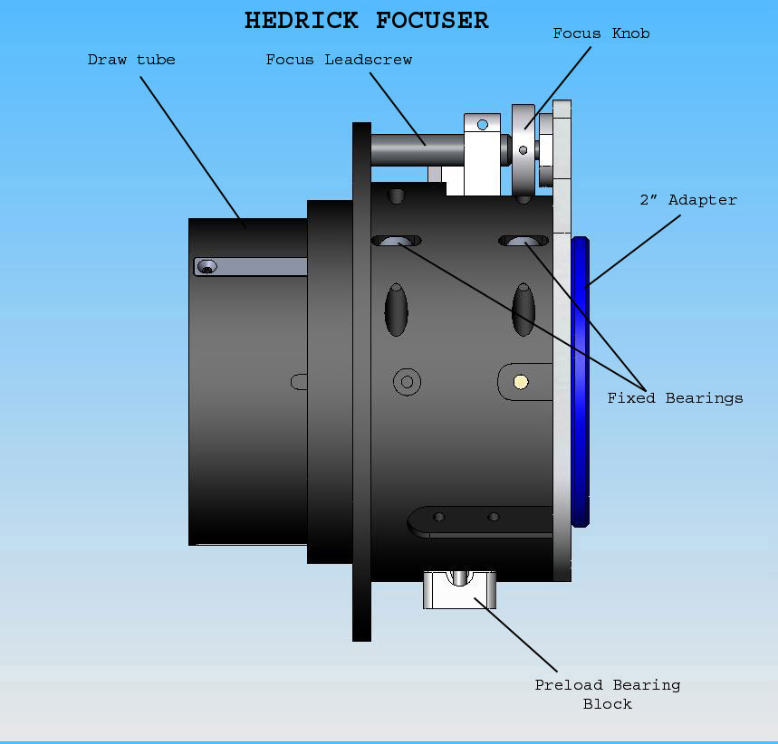
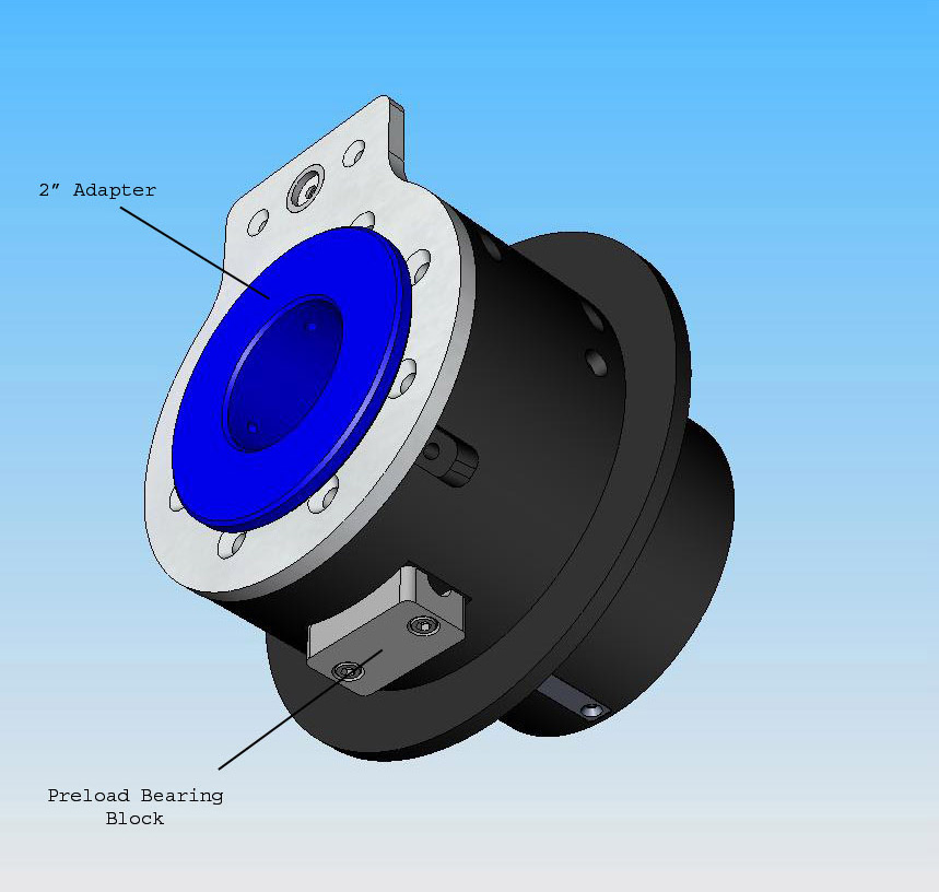
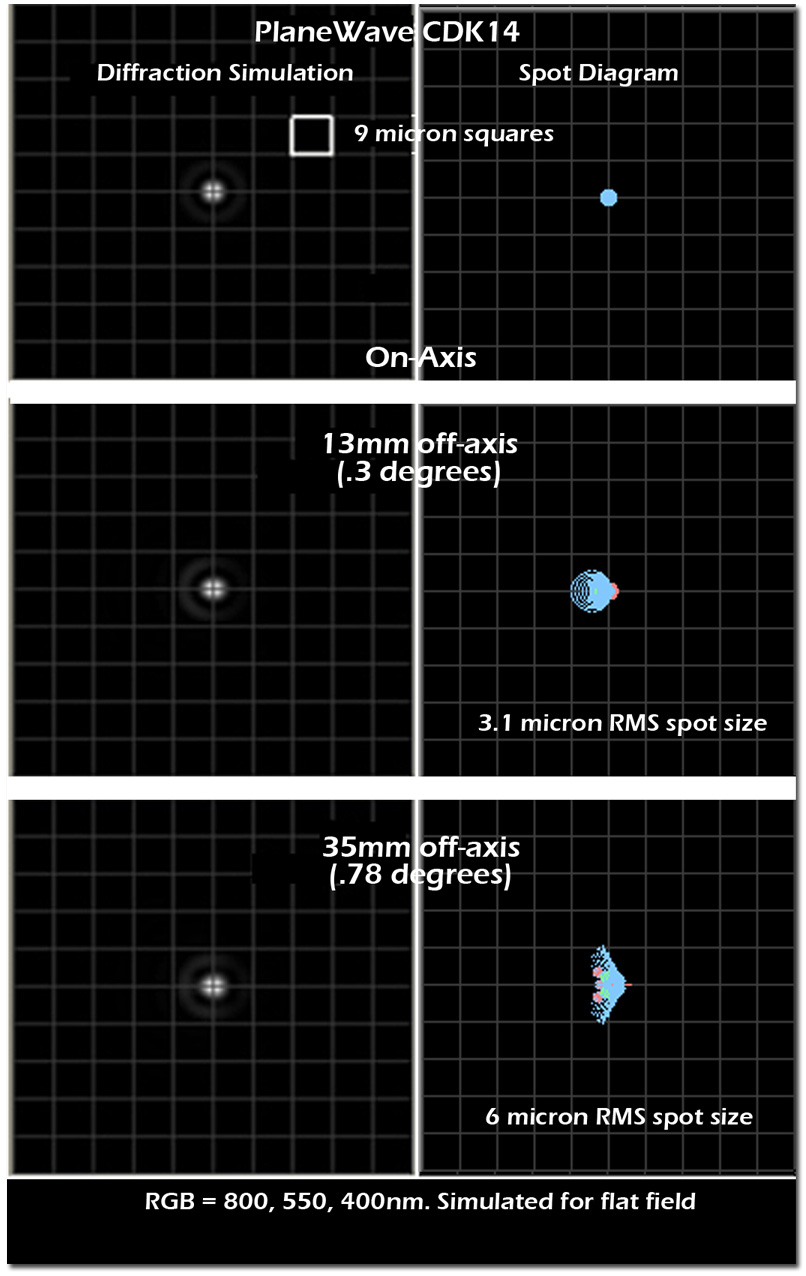
- Choosing a selection results in a full page refresh.
- Opens in a new window.